Dual zone feedwell for a thickener

a thickener and feedwell technology, applied in the field of separation devices, can solve the problems of increasing cost and space requirements, known extraction devices do not optimise mixing and distribution, etc., and achieve the effect of facilitating separation

Active Publication Date: 2005-06-02
OUTOKUMPU OY +1
View PDF14 Cites 34 Cited by
  • Summary
  • Abstract
  • Description
  • Claims
  • Application Information

AI Technical Summary

Benefits of technology

[0019] allowing said liquid suspension or pulp to flow from said...

Problems solved by technology

Known extraction devices do not optimise the mixing and distribution of liquid entering the thickening tank from the feedwell outlet.
They suffer from back-mixing of liquid from the thickening tank into the feedwell as well as short-c...

Method used


Image

  • Dual zone feedwell for a thickener
  • Dual zone feedwell for a thickener
  • Dual zone feedwell for a thickener

Examples


Embodiment Construction

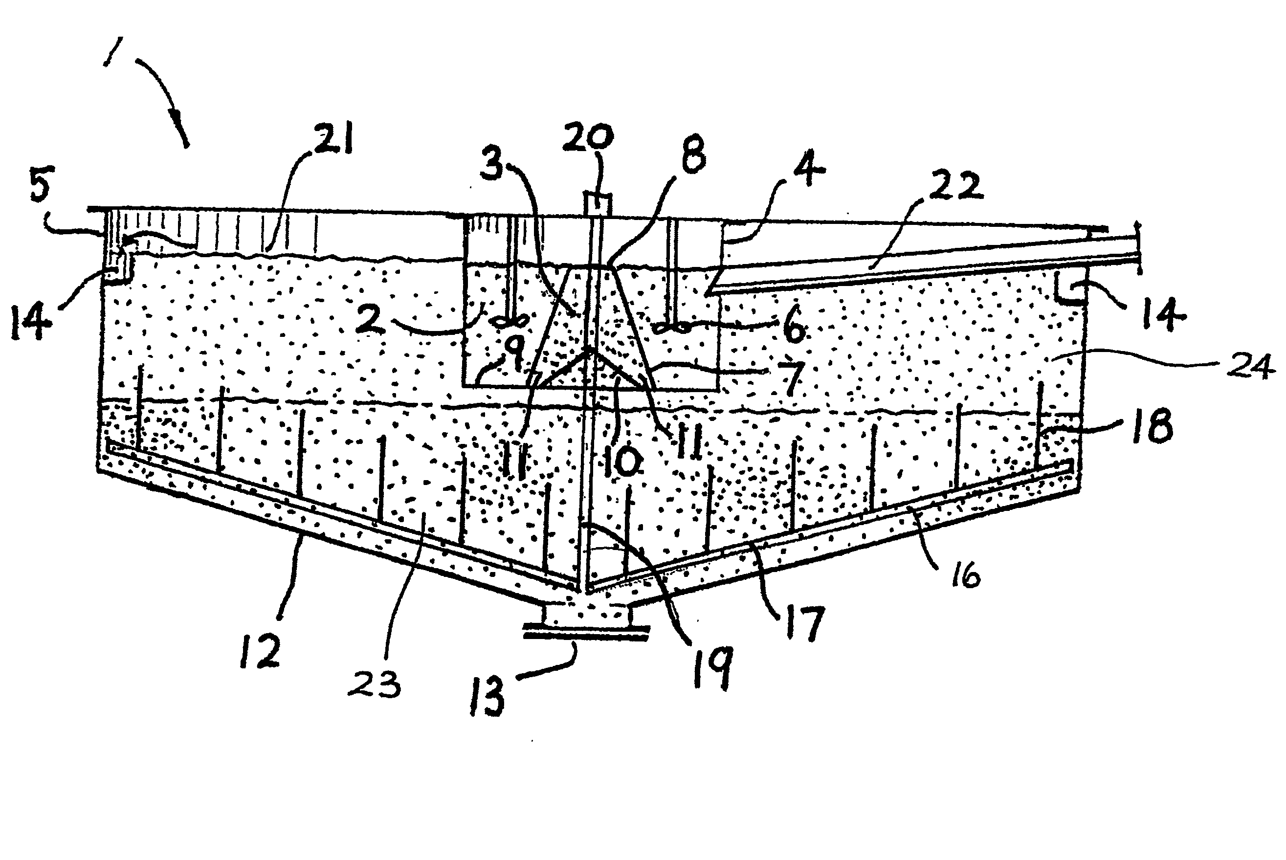
[0024] A preferred application of the invention is in the fields of mineral processing, separation and extraction, whereby finely ground ore is suspended as pulp in a suitable liquid medium such as water at a consistency which permits flow, and settlement in quiescent conditions. The pulp is precipitated from the suspension by a combination of chemical and mechanical processes. Initially, coagulant is added and mixed into the suspension in a first chamber, followed by the addition of flocculant in a second chamber. The suspension is then carefully mixed to facilitate the clumping together of solid particles, eventually forming larger denser particles that are precipitated out of suspension.

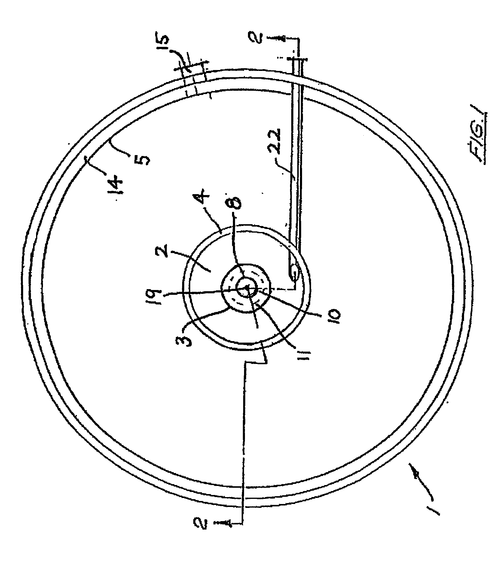
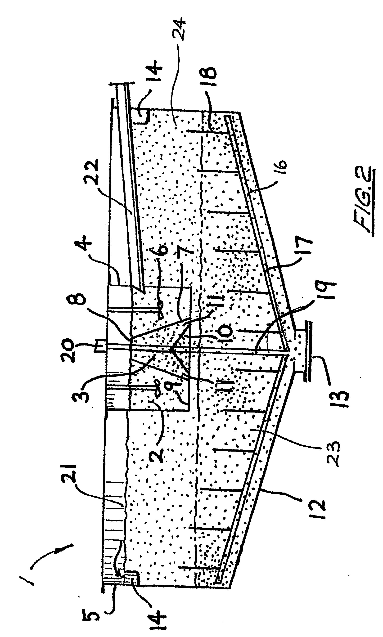
[0025] Referring to the drawings, the extraction device 1 includes two adjacent upstream and downstream concentric chambers 2 and 3 defining a feedwell 4. The feedwell is centrally located upstream of a third chamber in the form of a thickening tank 5. All three chambers are in sequential unidire...


PUM

PropertyMeasurementUnit
Flow rateaaaaaaaaaa
Areaaaaaaaaaaa

Abstract

The invention provides an extraction device (1) for liquid suspensions and pulps and is designed for use in the field of mineral processing. The extraction device includes two adjacent upstream and downstream concentric chambers (2) and (3) defining a feedwell (4). The feedwell is centrally located upstream of a third chamber in the form of a thickening tank (5). All three chambers are in sequential unidirectional fluid flow relationship such that feed liquid flows firstly from chamber (2) to chamber (3) and then to the tank (5).

Description

FIELD OF THE INVENTION [0001] The present invention relates to separation devices for liquid suspensions and pulps and in particular to a feedwell for use in such devices. It has been developed primarily for use in thickeners and will be described hereinafter with reference to this application. However, it will be appreciated that the invention is not limited to this particular field of use. BACKGROUND OF THE INVENTION [0002] The following discussion of the prior art is intended to present the invention in an appropriate technical context and allow its significance to be properly appreciated. Unless clearly indicated to the contrary, however, reference to any prior art in this specification should not be construed as an admission that such art is widely known or forms part of common general knowledge in the field. [0003] Known separation devices of this type typically include a thickening tank and a feedwell disposed generally within the tank to contain feed slurry. The feedwell is ...

Claims


Application Information

Patent Timeline
IPC IPC(8): B01D21/02B01D21/01B01D21/18B01D21/24C02F1/52
CPCB01D21/01B01D21/02B01D21/06B01D21/08B01D21/2405B01D21/2427B01D2221/04B01D21/286
Inventor TAYLOR, DAVID JOHN BUCHANAN
Owner OUTOKUMPU OY
Why Eureka
Try Eureka