Microfabricated ultrasonic transducer array for 3-D imaging and method of operating the same

a technology of ultrasonic transducers and microfabricated ultrasonic transducers, which is applied in the field of ultrasonic transducers, can solve the problems of mechanical translation suffering from several disadvantages, cost, reliability, mechanical jitter, etc., and the design and manufacture of the interconnect that connects an individual transducer element to its controlling circuitry can be difficult and expensiv

Inactive Publication Date: 2005-06-02
SIEMENS MEDICAL SOLUTIONS USA INC
View PDF29 Cites 60 Cited by
  • Summary
  • Abstract
  • Description
  • Claims
  • Application Information

AI Technical Summary

Benefits of technology

[0012] The present invention provides a capacitive microfabricated transducer array with a large elevation aperture, array elements connected to transmit and receive circuitry with azimuth connections, and bias line control of subsets of each array element's constituent diaphragms aligned in the elevation direction. A significant part of the aperture is off for a transmit-receive cycle. An off region of the aperture is implemented by alternating the bias in the elevation electrodes with sufficiently fine spatial resolution so as to cancel the acoustic fields generated and received by the affected elements. Alternatively, the elevation aperture can be turned off by applying a sufficiently high bias such that membranes touch down on the substrate, and thus do not respond at the frequencies of interest. Yet another way to selectively turn off a region of aperture is to provide zero bias to that region. Translation of the aperture is achieved by applying a different off-region bi

Problems solved by technology

Mechanical translation suffers from several disadvantages, among them cost, reliability, and mechanical jitter.
One disadvantage of 3-D imaging systems based on 2-D transd

Method used


Image

  • Microfabricated ultrasonic transducer array for 3-D imaging and method of operating the same
  • Microfabricated ultrasonic transducer array for 3-D imaging and method of operating the same
  • Microfabricated ultrasonic transducer array for 3-D imaging and method of operating the same

Examples


Embodiment Construction

[0022] The present invention will now be described in detail with reference to the drawings, which are provided as illustrative examples of the invention so as to enable those skilled in the art to practice the invention. Notably, the figures and examples discussed below are not meant to limit the scope of the present invention. Moreover, where certain elements of the present invention can be partially or fully implemented using known components, only those portions of such known components that are necessary for an understanding of the present invention will be described, and detailed descriptions of other portions of such known components will be omitted so as not to obscure the invention.

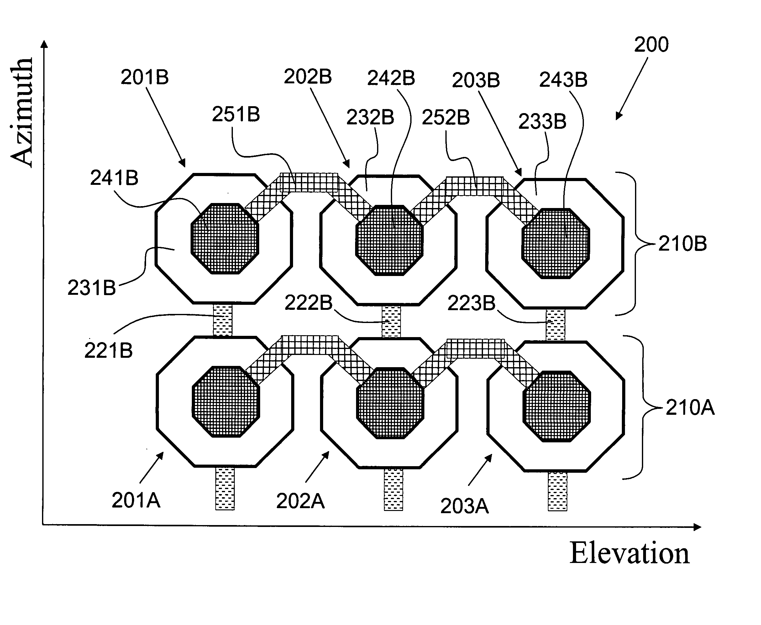
[0023]FIGS. 2 and 3 illustrate a cMUT array formed according to an embodiment of the present invention. It will become apparent to one skilled in the art that any number of transducer cells can make up a transducer element, and any number of transducer elements can make up a cMUT array. The pres...


PUM


Abstract

A capacitive microfabricated transducer array used for 3-D imaging, with a relatively large elevation dimension and a bias control of the elevation aperture in space and time, confers the same benefits of mechanical translation, except that image cross-sections are electronically rather than mechanically scanned, and are registered very accurately in space. The 3-D cMUT, when combined with elevation bias control and convex curvature in elevation, increases the volume interrogated by the electronic scanning, thus improving field of view. Further still, the 3-D cMUT can be combined Fresnel focusing of the elevation section to improve the elevation focus.

Description

CROSS-REFERENCE TO RELATED APPLICATIONS [0001] The present application claims priority to U.S. Provisional Application Ser. No. 60 / 508,481 filed Oct. 3, 2003, and is a continuation-in-part of, and claims the benefit of priority under 35 USC 120 from, commonly-owned U.S. patent application Ser. No. 10 / 819,094 to Panda et al. (hereinafter, “the '094 application”) and its previously filed Provisional Application 60 / 460,638, entitled “Method and Apparatus for Improving the Performance of Capacitive Acoustic Transducers using Bias Polarity Control and Multiple Firings,” the contents of which are incorporated herein by reference in their entirety and for all purposes, and which is a continuation-in-part of commonly-owned U.S. patent application Ser. No. 10 / 367,106 to Daft et al. (hereinafter, “the '106 application”), entitled “Microfabricated Ultrasonic Transducers with Bias Polarity Beam Profile Control and Method of Operating the Same,” the content of which is incorporated herein by ref...

Claims


Application Information

Patent Timeline
IPC IPC(8): A61B8/14B06B1/02G01S15/89
CPCB06B1/0292G01S15/8993G01S15/8925
Inventor LADABAUM, IGALPANDA, SATCHIDAFT, CHRISTOPHER M.
Owner SIEMENS MEDICAL SOLUTIONS USA INC
Why Eureka
Try Eureka