Method and device for the coordinated control of mechanical, electrical and thermal power flows in a motor vehicle

Inactive Publication Date: 2005-06-02
ROBERT BOSCH GMBH
View PDF8 Cites 6 Cited by
  • Summary
  • Abstract
  • Description
  • Claims
  • Application Information

AI Technical Summary

Benefits of technology

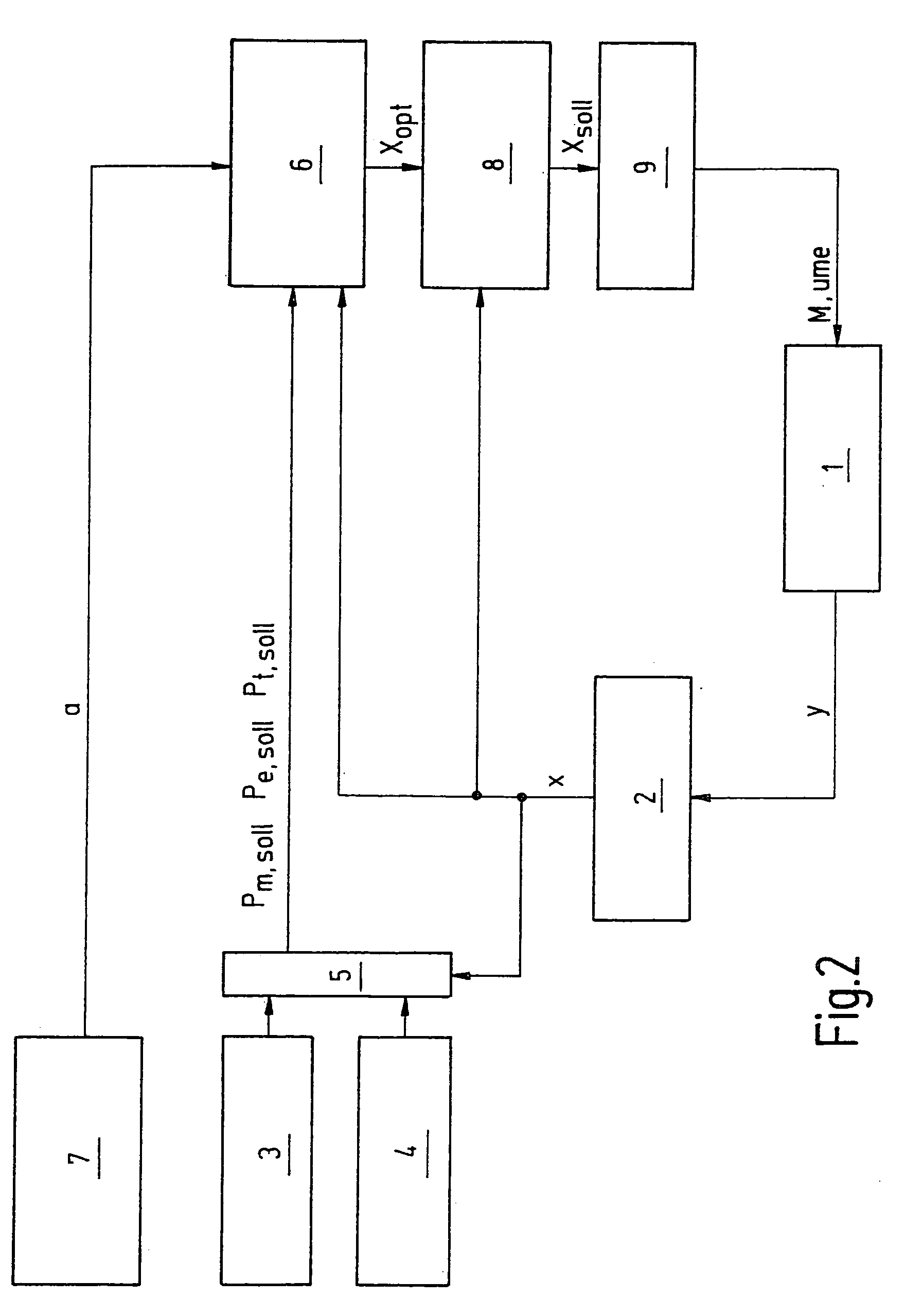
[0014] For carrying out the method for the coordinated control of mechanical, electrical and thermal power flows in a motor vehicle, the present invention also provides for a device in which an engine control associated with the internal combustion engine, a control, preferably in the form of a pulse-controlled inverter, associated with the electric machine, and a transmission control associated with the automatic transmission are connected via a CAN system to a vehicle control device in which the method according to the present invention is implemented, the position of the accelerator pedal and thus the driver's request for mechanical power Pm,setpoint for the drive being derivable using the vehicle control device. The vehicle control device specifies setpoint engine torque Mm,setpoint for the engine control, setpoint torque Me,setpoint of the electric machine for the pulse-controlled inverter, and setpoint gear gsetpoint for the transmission control. In addition, by use of this device, electrical power requirement Pe,setpoint of the electrical consumers, as well as that of the pulse-controlled inverter connected to the onboard electrical system and that of the battery, may be determined by the vehicle control device.

Problems solved by technology

However, conventional methods and systems share the common feature that they are principally concerned with only one form of energy in the mechanical, electrical, or thermal power flows in a motor vehicle, and, therefore, essentially do not take into account the physical linkage provided in a motor vehicle between these forms of energy.

Method used


Image

  • Method and device for the coordinated control of mechanical, electrical and thermal power flows in a motor vehicle
  • Method and device for the coordinated control of mechanical, electrical and thermal power flows in a motor vehicle
  • Method and device for the coordinated control of mechanical, electrical and thermal power flows in a motor vehicle

Examples


Embodiment Construction

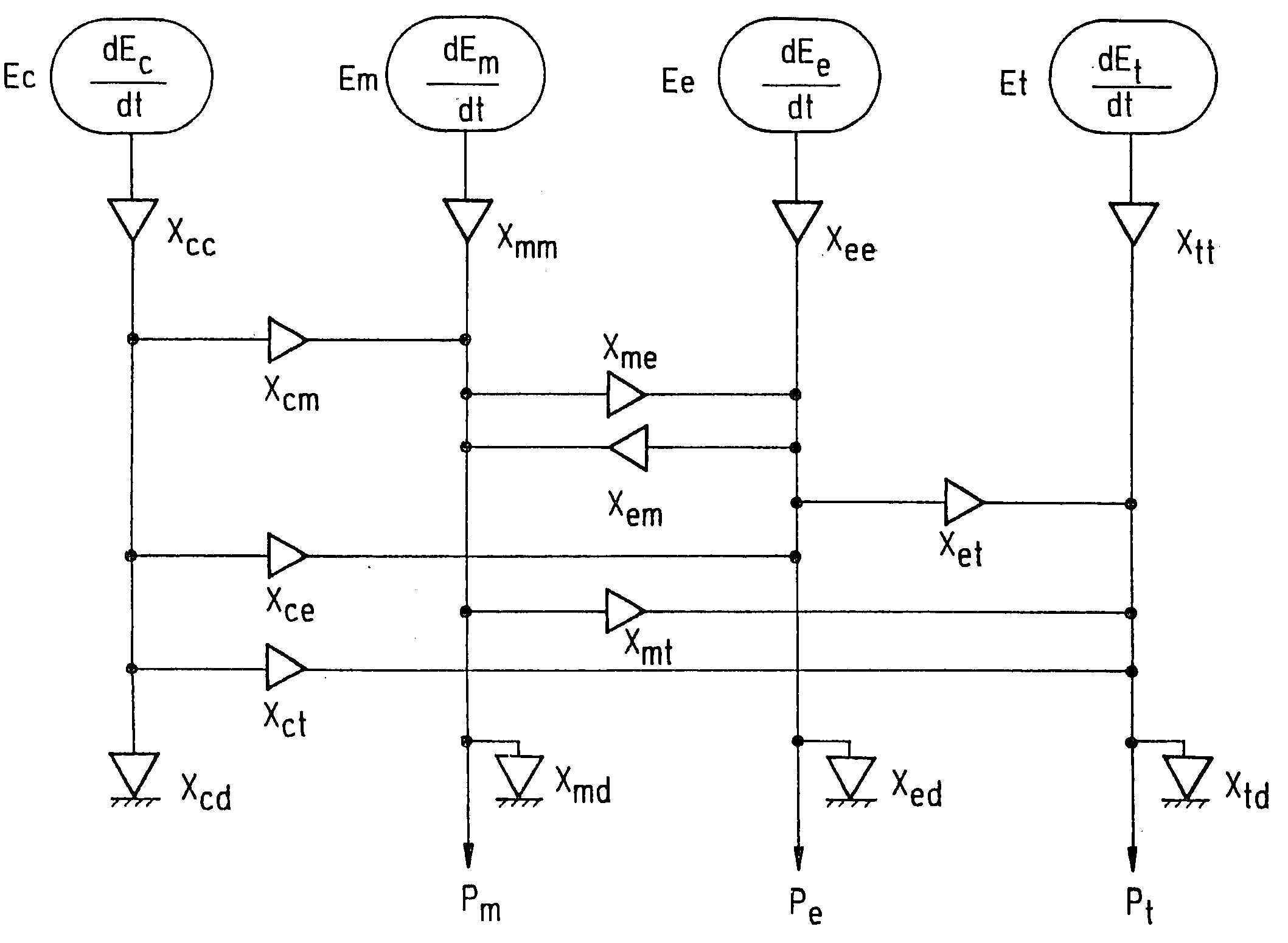
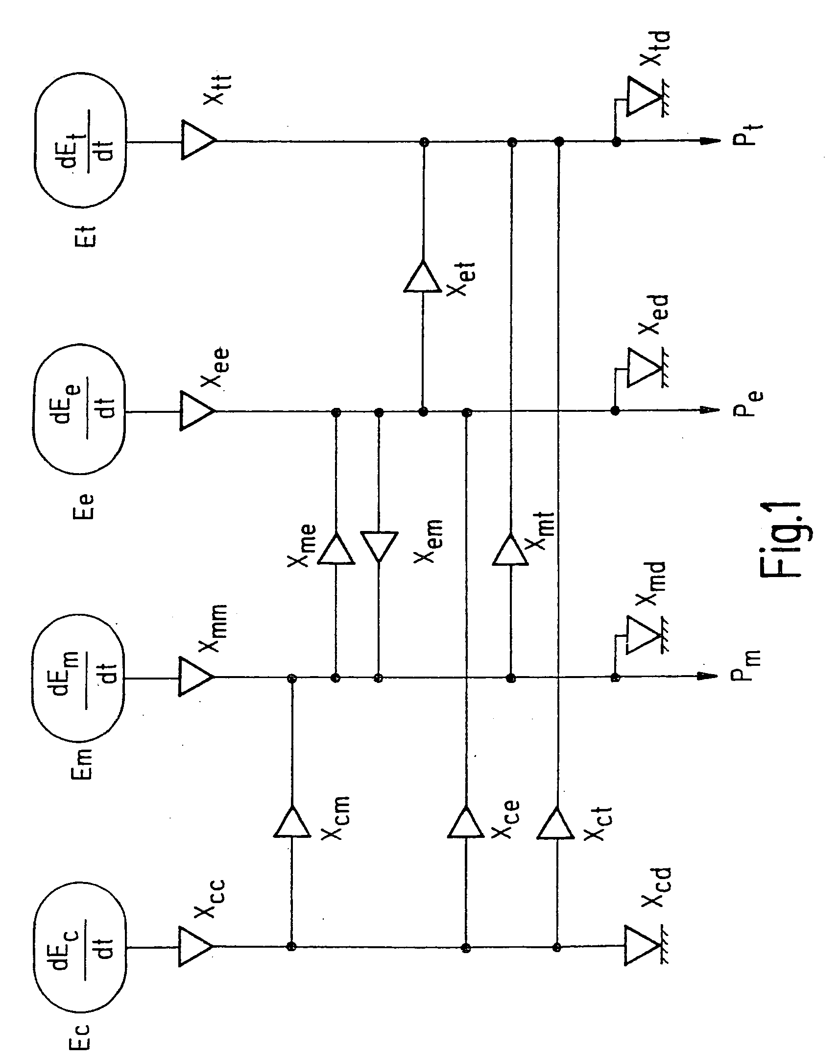
[0019] The unit system according to FIG. 1 provides mechanical power Pm, electrical power Pe, and thermal power Pt. The unit system may include chemical, mechanical, electrical and thermal storage units whose energy contents may each increase, decrease, or remain constant. The energy content of the chemical storage may be represented by Ec, that of the mechanical storage by Em, that of the electrical storage by Ee, and that of the thermal storage by Et. The rate of change of the energy content of the chemical storage is dEc / dt, that of the mechanical storage dEm / dt, that of the electrical storage dEe / dt, and that of the thermal storage dEt / dt. The operating state of each of the units may be characterized by a vector xi whose elements describe the state variables of the unit, for example rotational speed, torque, temperature and electrical current. For example: [0020] The operating state of a converter of chemical to mechanical energy, an internal combustion engine, for example, is d...


PUM


Abstract

A method for the coordinated control of mechanical, electrical and thermal power flows in a motor vehicle for bringing about optimum operating states of units in the motor vehicle, and a device for carrying out the method. An optimum operating state (xopt) for the unit system is determined in a module which receives as input variables at least the setpoint values provided by a second module after the variables determined by a third module have been combined together with additional specified variables in the second module, and the actual operating state (x) from a fourth module after the measured variables (y) resulting from the determination of the state of the units of the unit system have been combined in the fourth module; and after the optimum operating state (xopt) for the unit system is determined, the setpoint operating state (xsetpoint) is determined in a fifth module, based on the actual operating state (x) and the optimum operating state (xopt), so that due to this fifth module, a smooth transition is effected between the instantaneous operating state (x) and the operating state (xopt) to be achieved.

Description

FIELD OF THE INVENTION [0001] The present invention relates to a method for the coordinated control of mechanical, electrical and thermal power flows in a motor vehicle, such as, for example, the drive power to the wheels, the rear window heating and the interior climate control, for optimizing the consumption, comfort, emissions and dynamic vehicle response, and therefore for bringing about optimum operating states of units in the motor vehicle, including the storage systems, converters, transformers and the units for dissipating energy; the invention also relates to a device for carrying out the method for continuous control. BACKGROUND INFORMATION [0002] A number of conventional methods and devices for carrying out these methods exist for controlling power flows in a motor vehicle. DE 197 03 863 A1, for example, describes a method and a device by which a drive control is carried out, thus mechanical power flows in the motor-vehicle drive are controlled (see also Hötzer, D.: Entwi...

Claims


Application Information

Patent Timeline
Patent Type & Authority Applications(United States)
IPC IPC(8): B60K6/485B60K31/00B60W10/00B60W10/04B60W10/06B60W10/08B60W10/10B60W10/26B60W10/30B60W20/00F02D29/00F02D29/02F02D45/00
CPCB60K6/485B60W10/06B60W10/08Y02T10/6286B60W10/30B60W20/00Y02T10/6226B60W10/10Y02T10/40Y02T10/62
Inventor LOEFFLER, JUERGEN
Owner ROBERT BOSCH GMBH
Why Eureka
Try Eureka