Rotor selection interface and method

Active Publication Date: 2005-06-02
THERMO FISHER SCI ASHEVILLE
View PDF19 Cites 49 Cited by
  • Summary
  • Abstract
  • Description
  • Claims
  • Application Information

AI Technical Summary

Benefits of technology

[0005] The foregoing needs are met, to a great extent, by the present invention, wherein in one respect an apparatus an

Problems solved by technology

However, the large number of compatible rotors can make this a laborious and difficult process.
While this may be an improvement, there are still large numbers of rotors in a sub-population (

Method used


Image

  • Rotor selection interface and method
  • Rotor selection interface and method
  • Rotor selection interface and method

Examples


Example

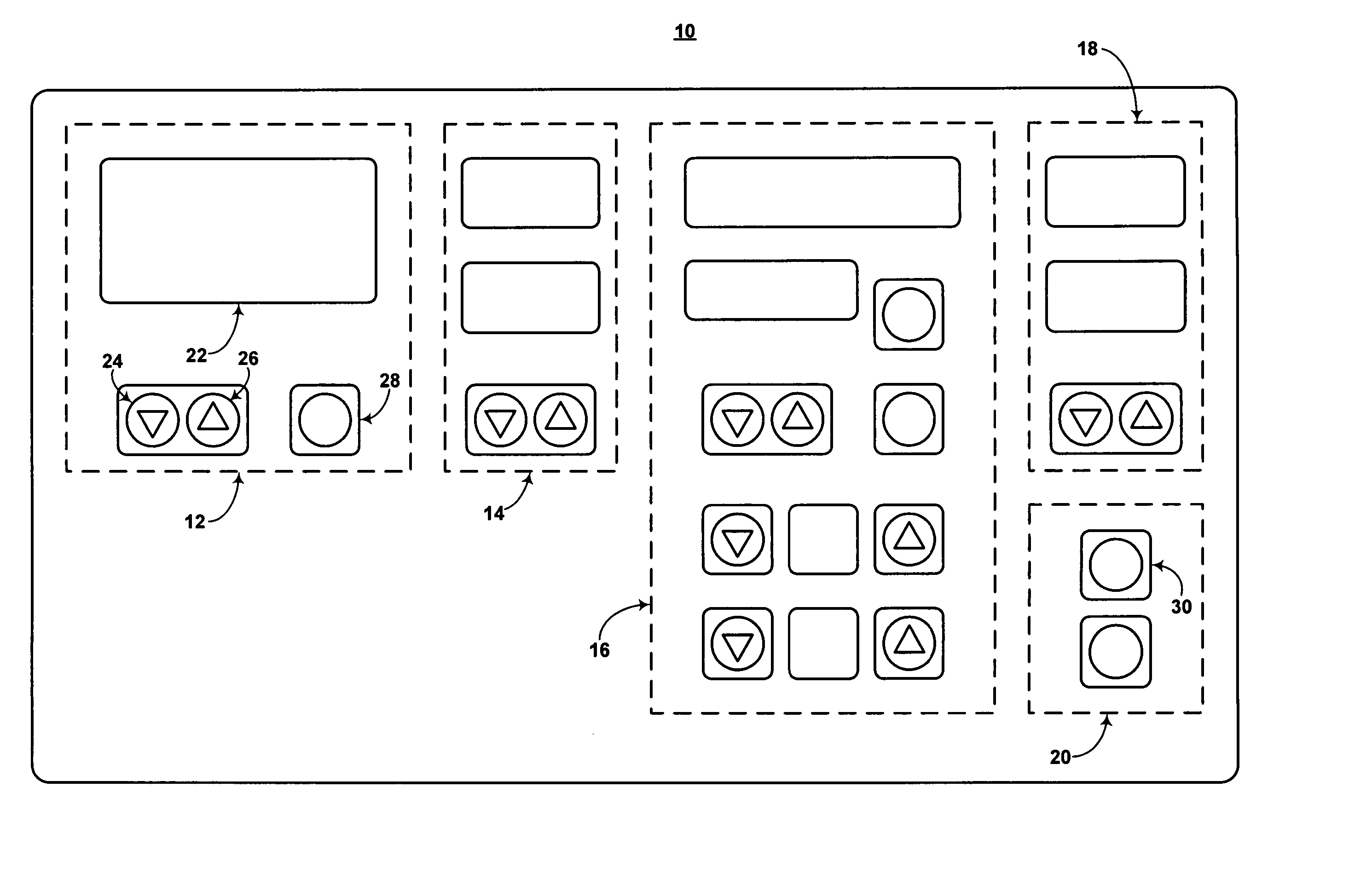
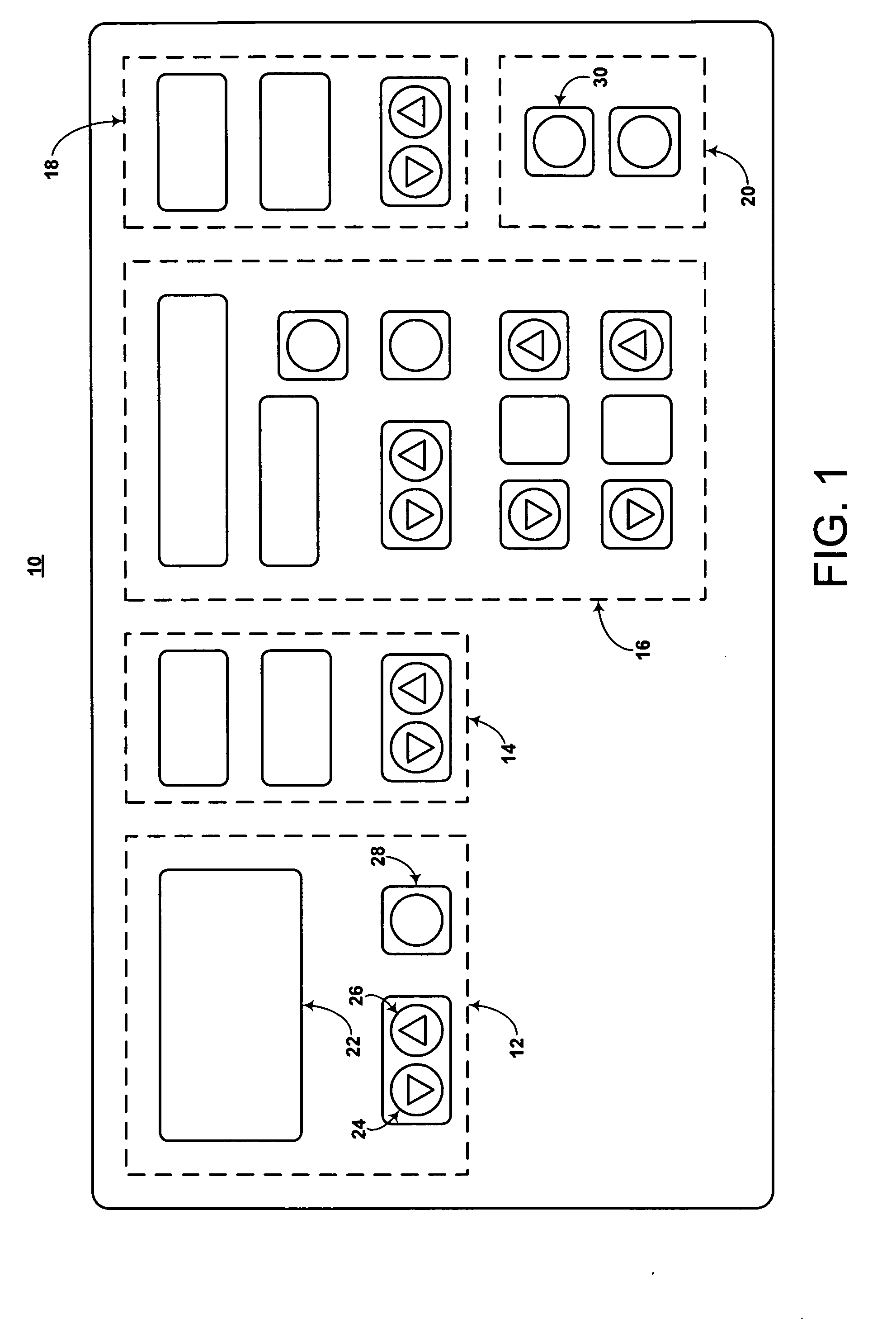
[0022] The present invention provides a user interface device for a centrifuge and a method of selecting a rotor for use in the centrifuge. In some embodiments, the user interface device includes a plurality of switches for selecting a particular rotor from a list of compatible rotors and at least one display to display these rotors. The type or types of switches utilized includes any suitable device. Specific examples of suitable switches include: mechanical and solid state toggles; mechanical and solid state buttons; computer programmed icons or virtual toggles and / or switches; rotary dial; and / or the like. In this regard, the switches may be incorporated into the display such as, for example, a touch screen. The display includes any suitable display device. Specific examples of suitable displays include: liquid crystal displays (LCD); cathode ray tube (CRT); thin film transistor (TFT); color super-twist nematic (CSTN); high performance addressing (HPA); organic light emitting dio...


PUM


Abstract

In a user interface to select a desired rotor from a set of rotors corresponding to compatible rotors for use in a centrifuge device, a home menu is utilized to access a previously selected rotor and an add menu is utilized to add the desired rotor in response to the desired rotor being absent from the home menu. In addition, the add menu includes the set of rotors.

Description

FIELD OF THE INVENTION [0001] The present invention generally relates to a selection interface device and method. More particularly, the present invention pertains to an interface device and method for selecting a centrifuge rotor from a plurality of rotors. BACKGROUND OF THE INVENTION [0002] Centrifuges are typically designed to run a population of rotors. In this regard, a given centrifuge system may include upwards of 30 or more compatible rotors. It is important to know which rotor is being used as performance parameters are impacted by rotor characteristics. For example, the performance parameters of Relative Centrifugal Force (RCF) mode are calculated based on the location of the sample in the rotor. Therefore, rotor identification and tracking devices have been incorporated into some conventional centrifuges. For example, some conventional centrifuges include a display to present a list of compatible rotors to a user and toggle switches to provide the user with a scrolling an...

Claims


Application Information

Patent Timeline
IPC IPC(8): B04B13/00
CPCB04B13/00
Inventor HALL, RICHARD A.
Owner THERMO FISHER SCI ASHEVILLE
Why Eureka
Try Eureka