Continuous Substrate Processing Apparatus

a processing apparatus and substrate technology, applied in the direction of vacuum evaporation coating, chemical vapor deposition coating, coating, etc., can solve the problems of unfavorable mass production, defective devices, and above-described roll-to-roll process system suffers from a number, so as to achieve the effect of increasing mass production productivity

Inactive Publication Date: 2014-11-06
AREESYS
View PDF6 Cites 29 Cited by
  • Summary
  • Abstract
  • Description
  • Claims
  • Application Information

AI Technical Summary

Benefits of technology

[0007]The present application discloses highly modularized processing systems using continuous flexible substrates. The disclosed processing systems offer flexibility in process, scalability from development, pilot to production, as well as higher productivity in mass production. The continuous flexible substrate may be flexible polymer webs, metal foils, papers, etc. The continuous flexible substrate can also serve as a carrier on which small, rigid substrates or low profile 3-dimentional workpieces are mounted.
[0009]Because of their flexibility and modularity, the disclosed processing systems can fully utilize the process window of each process technique without causing interferences between different techniques.
[0010]The disclosed processing systems can eliminate or minimize cross contaminations that are usually associated with conventional single-chamber roll-to-roll processing systems.

Problems solved by technology

The above described roll-to-roll process system suffers from a number of major drawbacks.
The cross contamination between the deposition sources can cause unwanted process drifts in production, and defective devices.
Moreover, it is very difficult to implement depositions of very different atmospheres in the same vacuum chamber.
Furthermore, the throughput of the web-based system 100 is limited by the slowest deposition source, which can significantly limit the productivity of the entire equipment.

Method used


Image

  • Continuous Substrate Processing Apparatus
  • Continuous Substrate Processing Apparatus
  • Continuous Substrate Processing Apparatus

Examples


Embodiment Construction

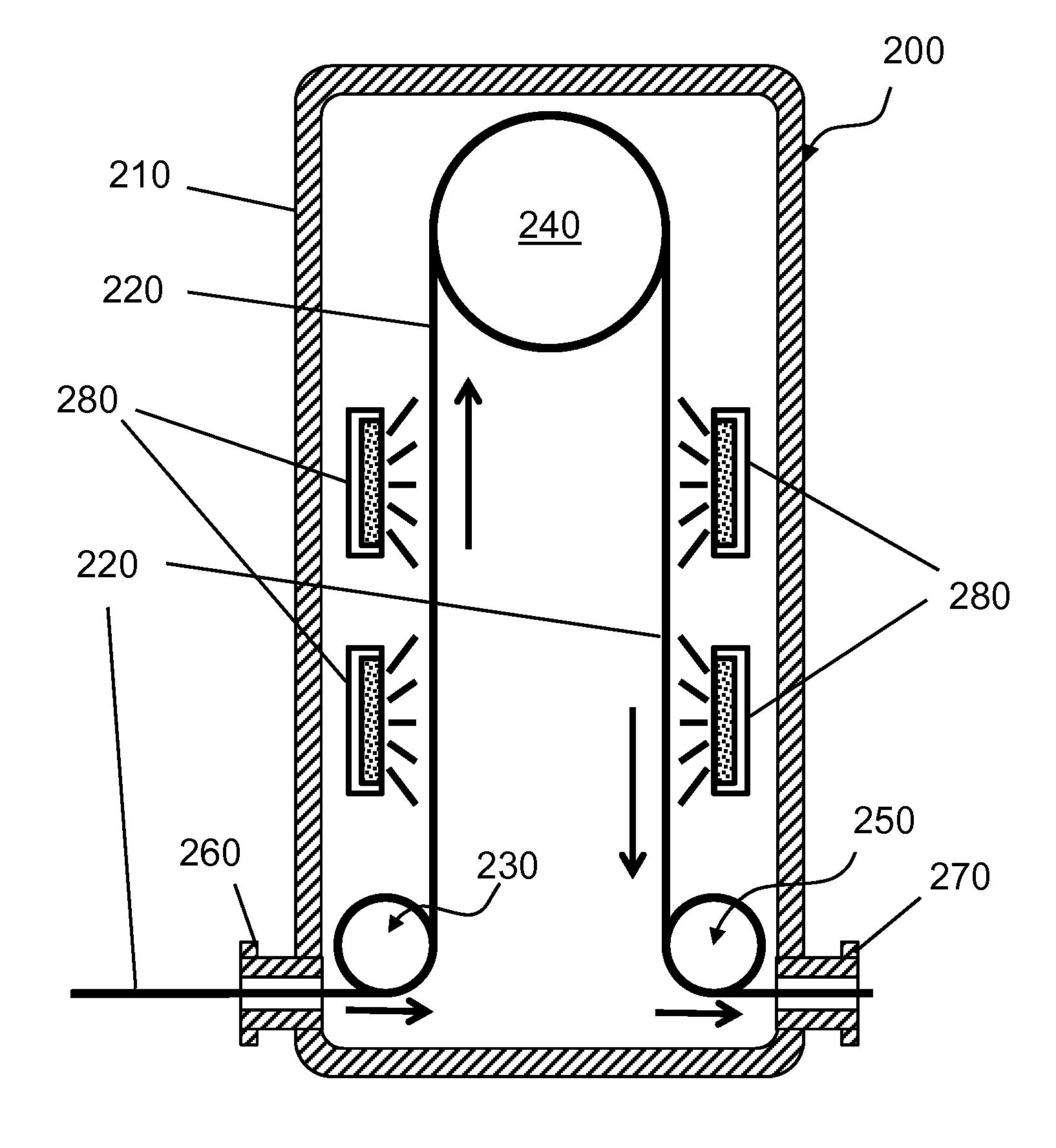
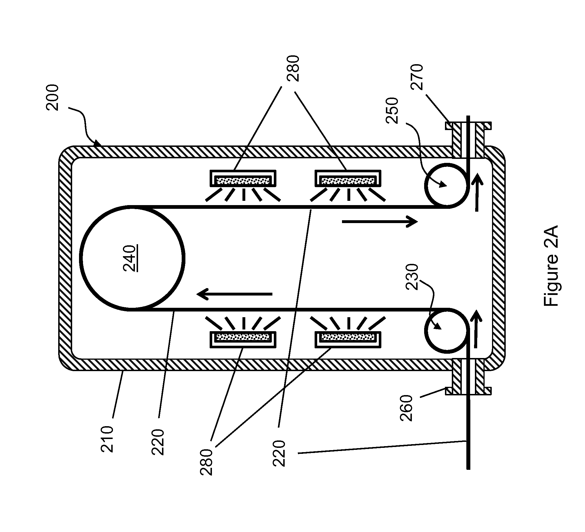
[0026]Referring to FIG. 2A, a processing module 200 includes a vacuum chamber 210, an entry slit 260 having a long, narrow opening and a vacuum sealing flange, a guiding roller 230, a wrap-around roller 240, another guiding roller 250, and an exit slit 270. The processing module 200 can also include a vacuum pumping port and pump (not shown) for maintaining vacuum in the vacuum chamber 210. A web substrate 220 is transported into the entry slit 260, guided by the guiding rollers 230, 250 and the wrap-around roller 240, and exits the vacuum chamber 210 through the exit slit 270. Processing sources 280 are mounted in two sides of the wrap-around roller 240 but facing the outer surface of the web substrate 220. As an example, the web substrate 220 can be 0.5 meter wide, 1000 meter long, and 0.1 mm thick. The web substrate 220 can be made of PET (polyethylene terephthalate). The processing sources 280 can provide different deposition materials for different deposition techniques such as...


PUM

PropertyMeasurementUnit
pressureaaaaaaaaaa
pressureaaaaaaaaaa
pressureaaaaaaaaaa

Abstract

A processing system includes a first processing module that includes a first chamber; and a first processing source that can deposit a first material on a web substrate. An isolation module includes an isolation chamber, and one or more segregation walls that define a sequence of compartments in the isolation chamber. The first chamber is connected to a first compartment in the sequence of compartments. Each of the segregation walls includes an opening to allow the web substrate to pass through. A second processing module includes a second chamber in connection with a last compartment in the sequence of compartments in the isolation module, and a second processing source configured to deposit a second material on the web substrate. A transport mechanism moves the web substrate continuously through the first processing module, the isolation module, and the second processing module.

Description

BACKGROUND OF THE INVENTION[0001]The present application relates to material deposition technologies, and more specifically to continuous deposition systems.[0002]Flexible sheet materials such as thin stainless steel foil, polymer web, and paper are widely used as substrates supporting thick films (˜100's microns) or thin films (˜10's to 100's nanometers) of other functional materials. Examples of common functional materials include metals, semiconductors, insulators, and inorganic, organic or composite materials. The functional materials can be deposited or coated by vacuum-based technologies (e.g. sputtering, thermal evaporation, electron-beam evaporation, plasma enhanced chemical vapor deposition and atomic layer deposition), or non-vacuum-based technologies (e.g. chemical bath deposition, spin-on, sol-gel, spray-on, screen printing and inkjet printing). Film process technology using flexible substrates is often called “roll-to-roll process” (RTR process), or “web process”. Roll-...

Claims


Application Information

Patent Timeline
Patent Type & Authority Applications(United States)
IPC IPC(8): B05C9/06
CPCB05C9/06B05C3/125C23C14/562C23C16/545H01J37/32403H01J37/3277H01J37/32807H01J37/32899H01J37/34
Inventor WANG, KAI-ANWONG, MICHAEL Z.
Owner AREESYS
Why Eureka
Try Eureka