
Method and apparatus for removing modular forms

a technology of modular forms and methods, applied in the field of methods and tools for building construction, can solve the problems of affecting the future use of forms, many forms are bent, broken, etc., and achieve the effect of facilitating the pulling of forms

Inactive Publication Date: 2005-06-09
FORM PULLER TOOL CO
View PDF2 Cites 23 Cited by
  • Summary
  • Abstract
  • Description
  • Claims
  • Application Information

AI Technical Summary

Benefits of technology

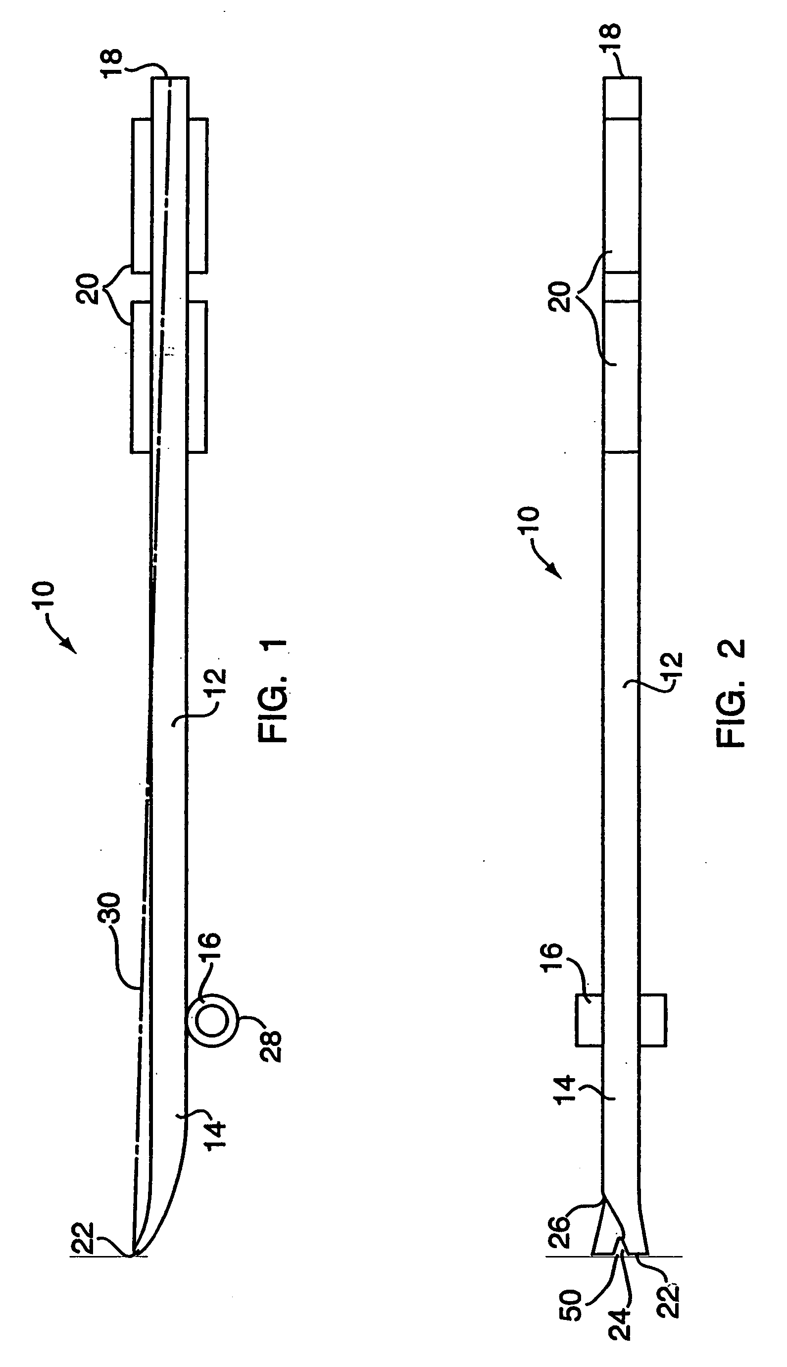
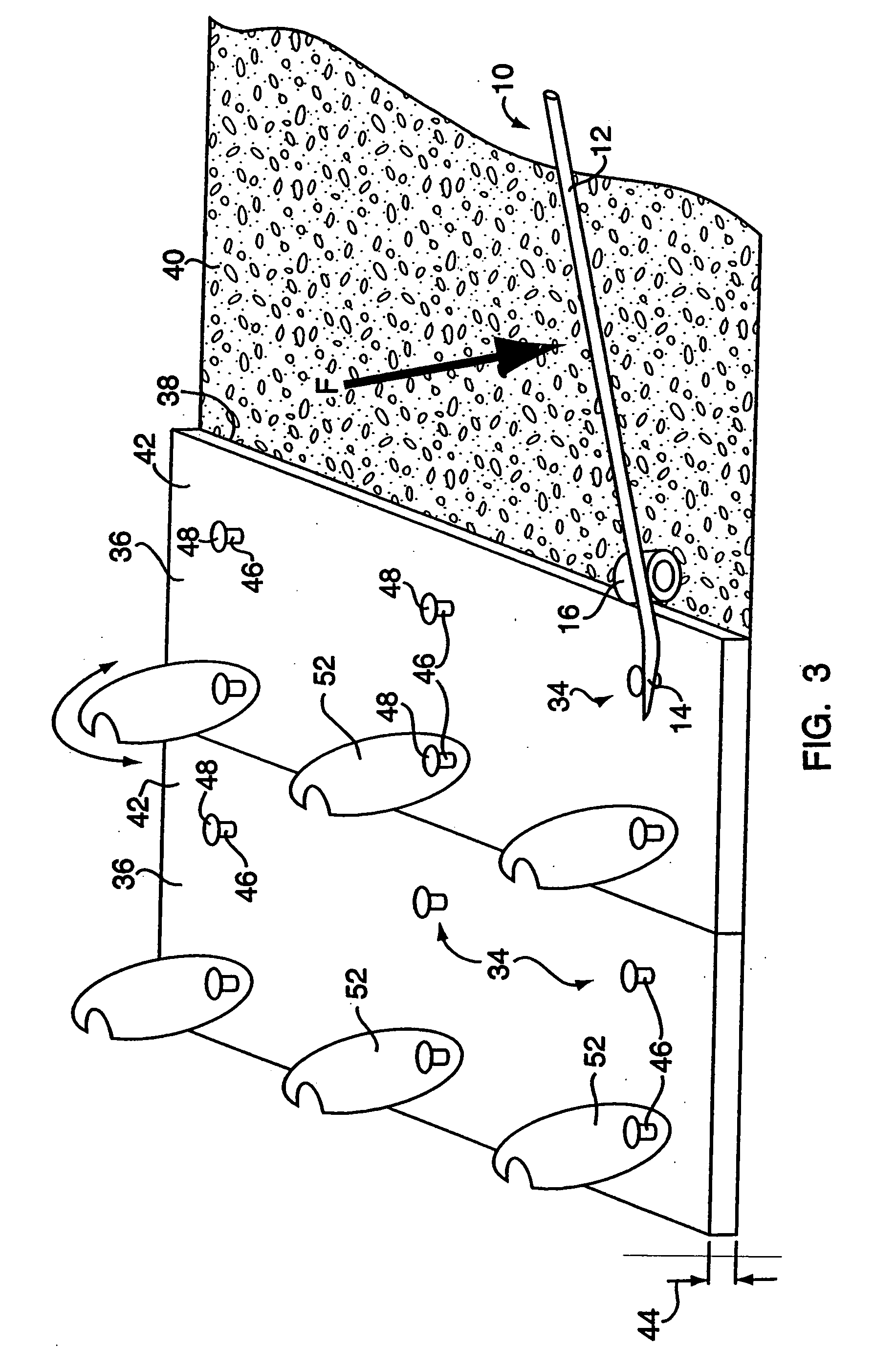
[0008] In a second aspect of the present invention, a method of removing modular forms includes providing an apparatus with a lever arm having a first longitudinal end and a second longitudinal end. A projection extends beyond the first longitudinal end for engaging a hole defined in a form. The projection extends in a direction generally parallel to a longitudinal axis of the lever arm. A fulcrum is coupled to the lever arm. The fulcrum is disposed closer to the first longitudinal end relative to the second longitudinal end. A knuckle guard is coupled to and disposed on a same side of the lever arm relative to the fulcrum. The knuckle guard is disposed closer to the second longitudinal end relative to the first longitudinal end. The projection is inserted into a hole defined in a frame of a form to be removed from a wall. The second longitudinal end of the lever arm is moved toward the wall so as to cause the lever arm to pivot on the fulcrum and move the projection away from the wall to thereby pull the form away from the wall. The projection is inserted into one or more additional holes defined in a frame of the form, if necessary, and the step of moving is repeated for each of the additional holes receiving the projection in order to facilitate pulling the form from the wall. Preferably, the step of inserting is repeated, if necessary, by selecting an upper hole defined in the frame of the form and then selecting one or more additional holes disposed progressively lower on the frame relative to the upper hole.

Problems solved by technology

Using the pry bar in this way tends to deform the edge or a surface of the modular form that hinders future use of the form.
Despite the release agent, many forms are bent, breached, or otherwise deformed during removal.

Method used


Image

  • Method and apparatus for removing modular forms
  • Method and apparatus for removing modular forms
  • Method and apparatus for removing modular forms

Examples


second embodiment

[0031] With reference to FIGS. 5 and 6, an apparatus for removing modular forms in accordance with the present invention is indicated generally by the reference number 110. Like elements with the apparatus 10 of FIGS. 1-4 are indicated by like reference numbers preceded by “1”. The apparatus 110 is generally the same as the apparatus 10 except for the lever arm or handle. Accordingly, the apparatus 110 and its operation will be described in detail only with respect to the structure that is different from that of the apparatus 10.

[0032] The apparatus 110 comprises a lever arm 112, a head or claw 114 at an end of the lever arm, and a fulcrum 116 disposed therebetween. The apparatus 110 is employed for removing forms such as, for example, 1⅛″ plywood style modular forms, in a manner similar to that explained with respect to the apparatus 10 shown in FIGS. 1-4. The lever arm 112 includes a first portion 113 and a second portion 115 which are oriented at an angle α with respect to each o...

third embodiment

[0036] Referring to FIG. 7, an apparatus for removing modular forms in accordance with the present invention is indicated generally by the reference number 210. Like elements with the apparatus of FIGS. 1-4 are indicated by like reference numbers preceded by “2”.

[0037] The apparatus 210 comprises a lever arm or handle 212 having a first longitudinal end 213 and a second longitudinal end 215. A projection 217 such as, for example, a hardened steel pin, extends slightly beyond the first longitudinal end 213 of the lever arm 212. A fulcrum 216, preferably in the form of a hollow cylinder, is coupled to the lever arm 212 at a first side 219 thereof, and is disposed therealong closer to the first longitudinal end 213 relative to the second longitudinal end 215. The apparatus 210 preferably includes a knuckle guard 221 coupled to the lever arm 212 at the first side 219 thereof, and is disposed therealong closer to the second longitudinal end 215 relative to the first longitudinal end 213....

fourth embodiment

[0041] Referring to FIGS. 8 and 9, an apparatus for removing modular forms in accordance with the present invention is indicated generally by the reference number 310. Like elements with the apparatus of FIGS. 1-4 are indicated by like reference numbers preceded by “3”.

[0042] The apparatus 310 is generally similar to the apparatus 10 of FIGS. 1-4 except that the apparatus 310 includes pulling heads on both ends of the handle. As shown in FIGS. 8 and 9, the apparatus 310 comprises a lever arm 312 having a first longitudinal end 311 and a second longitudinal end 313. The apparatus 310 further comprises a first head or claw 314 at the first longitudinal end 311 of the lever arm 312, a first fulcrum 316 associated with the first head and disposed along the lever arm 312 closer to the first longitudinal end 311 relative to the second longitudinal end 313. A second head or claw 315 is disposed at the second longitudinal end 313 of the lever arm 312, and a second fulcrum 317 associated wit...


PUM

PropertyMeasurementUnit
lengthaaaaaaaaaa
diameteraaaaaaaaaa
diameteraaaaaaaaaa

Abstract

A method and apparatus for removing modular forms includes a lever arm having a first longitudinal end and a second longitudinal end. A projection such as a hardened steel pin extends beyond the first longitudinal end for engaging a hole defined in a form. The projection extends in a direction generally parallel to a longitudinal axis of the lever arm. A fulcrum is coupled to the lever arm. The fulcrum is disposed closer to the first longitudinal end relative to the second longitudinal end. A knuckle guard is coupled to and is disposed on a same side of the lever arm relative to the fulcrum. The knuckle guard is disposed closer to the second longitudinal end relative to the first longitudinal end.

Description

CROSS-REFERENCE TO RELATED APPLICATIONS [0001] This is a continuation-in-part application of application Ser. No. 10 / 839,673, filed on May 5, 2004, which is a continuation-in-part of application Ser. No. 10 / 012,624, filed on Dec. 7, 2001, now U.S. Pat. No. 6,817,590 B2, the disclosures of which are herein incorporated by reference in their entireties.FIELD OF THE INVENTION [0002] This invention relates generally to methods and tools for building construction. It relates more particularly to a method and tool for removing modular forms from an underlying surface. BACKGROUND [0003] Certain building sections such as foundations for buildings or bridges are typically constructed with concrete for its advantages of high compressive strength, resistance to degradation by ground and water contact, and lower total cost as compared to stacked masonry units. These concrete building sections are usually framed by forms that create a mold into which fluid concrete is poured and cured. Forms may...

Claims


Application Information

Patent Timeline
Patent Type & Authority Applications(United States)
IPC IPC(8): B28B13/06E04G17/00E04G19/00
CPCB28B13/06E04G19/00E04G17/00
Inventor GARGIULO, EUGENE
Owner FORM PULLER TOOL CO
Learn More