Gasket of non-rounded shape with installation aids

Inactive Publication Date: 2005-06-09
GARLOCK SEALING TECHNOLOGIES
View PDF24 Cites 28 Cited by
  • Summary
  • Abstract
  • Description
  • Claims
  • Application Information

AI Technical Summary

Benefits of technology

[0013] In a further aspect of the present invention, a gasket assembly is provided comprising a substantially flat annular gasket core having two profiled faces and defining an aperture therethrough, said profiled faces comprising an alternating peak and groove configuration defined by angles of approximately 90°, and at least one installation tab secured to an outer periphery of said gasket core, wherein said gasket core comprises a metallic material and gasketing material is disposed upon the profiled faces.
[0014] In yet another aspect of the present invention, a gasket assembly is provided comprising a substantially flat annular stainless steel gasket core having two partially profiled faces and defining an aperture therethrough, said partially profiled faces comprising a radially spaced alternating peak and groove configuration defined by peak angles of approximately 90°, and four installation tabs secured to an outer periphery of said gasket core formed of a ductile material, wherein said gasket core comprises a gasketing material is disposed upon the profiled faces.
[0015] As will be realized by those of skill in the art, many different embodiments of a gasket according to the present invention are possible. Additional uses, objects, advantages, and novel features of the invention are set forth in the detailed description that follows and will become more apparent to those skilled in the art upon examination of the following or by practice of the invention.
[0016] Thus, there has been outlined, rather broadly, the more important features of the invention in order that the detailed description that follows may be better understood and in order that the present contribution to the art may be better appreciated. There are, obviously, additional features of the invention that will be described hereinafter

Problems solved by technology

This non-round configuration makes sealing by way of conventional gaskets difficult.
One substantial limitation of this design is the inability of the gasket to withstand high internal pressures.
This failure occurs in part because the gasket material does not sufficiently mechanically bond to the metal substrate, and therefore, has a limited amount of shear resistance to overcome high internal system pressures.
While these gasket types are effective in many sealing operations, particular problems arise when the gaskets are non-round in shape.
Unexpected or irregular deformation of the gasket, or improper

Method used


Image

  • Gasket of non-rounded shape with installation aids
  • Gasket of non-rounded shape with installation aids
  • Gasket of non-rounded shape with installation aids

Examples


example

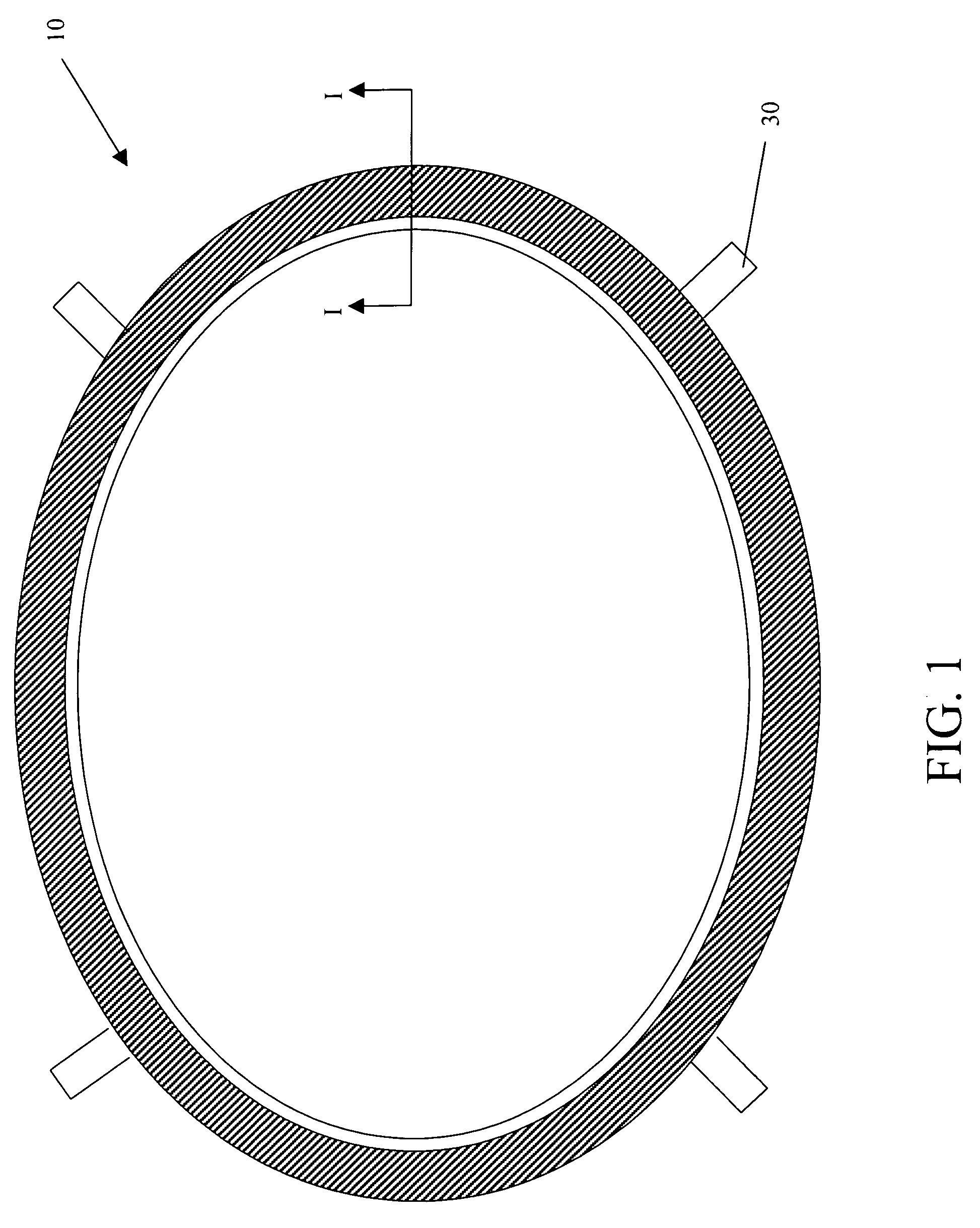
[0041] In one embodiment of the present invention, a non-round gasket assembly, in this example oval, with profiled surface and installation aids was manufactured in accordance with the following method. This gasket assembly is shown in FIGS. 1 and 4.

[0042] (1) A ⅛-inch thick 316L stainless steel plate was cut to a rectangle having long sides of 17 inches and short sides of 13 inches.

[0043] (2) The rectangle of ⅛-inch steel was then center punched.

[0044] (3) The rectangle was then circle-sheared to cut out an oval having a radially outer edge defining a major axis of 17 {fraction (14 / 16)} and a minor axis of 13 {fraction (14 / 16)}.

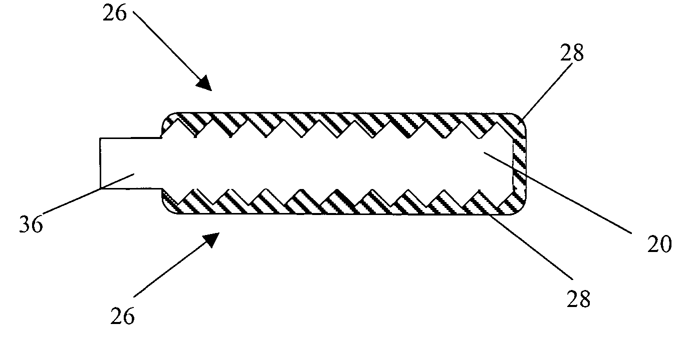
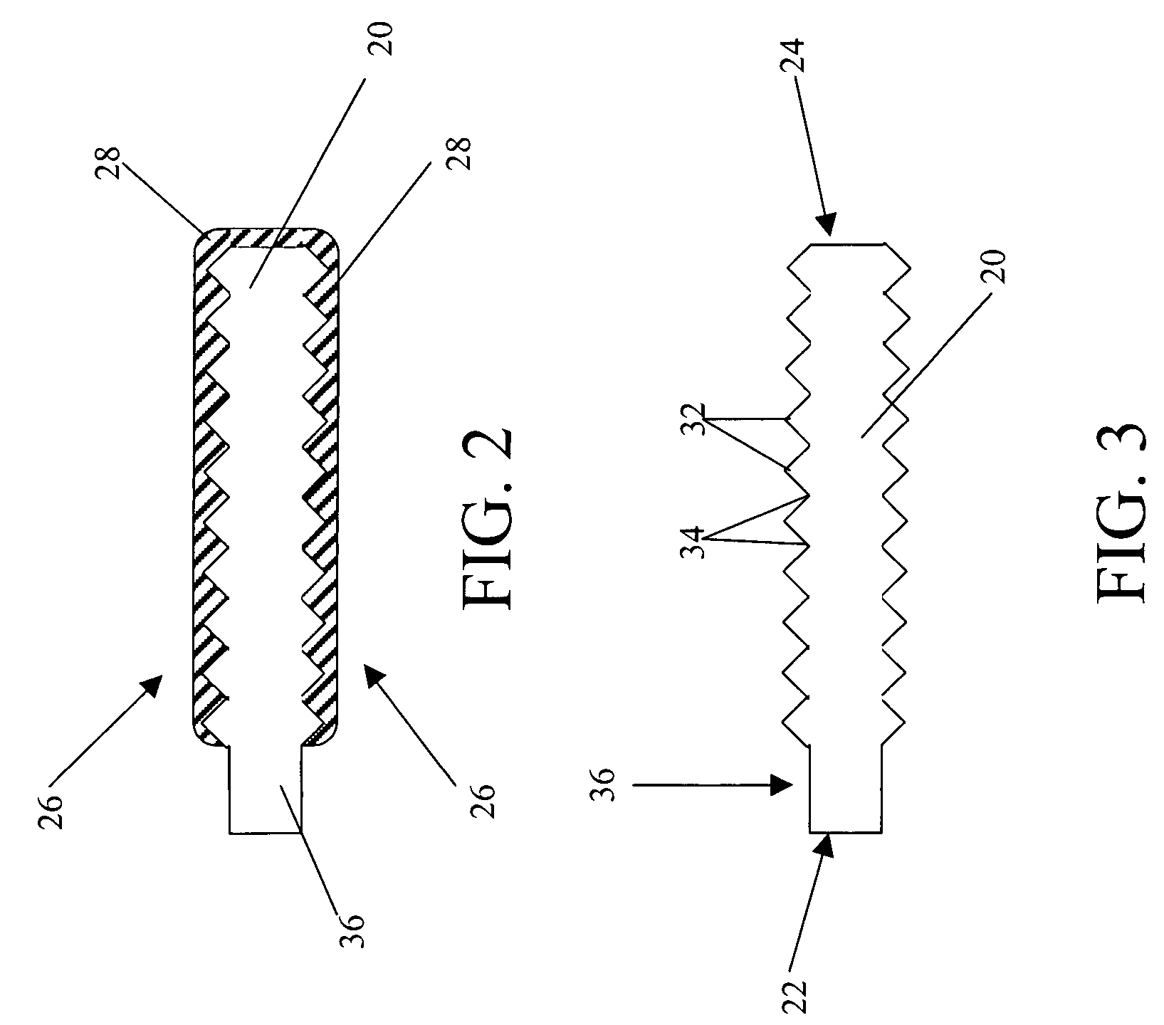
[0045] (4) The ⅛-inch thick oval was then profiled to cut {fraction (30 / 1000)}-inch deep grooves (B) in both faces of the gasket core having a peak to peak width (C) of {fraction (60 / 1000)} inches and a peak and groove angle θ of 90° resulting in approximately 16 ⅔ grooves / inch across the face of the gasket core. The grooves are preferably designed to f...


PUM


Abstract

A gasket assembly is comprising a substantially flat annular stainless steel gasket core having two partially profiled faces and defining an aperture therethrough, said partially profiled faces comprising a radially spaced alternating peak and groove configuration defined by peak angles of approximately 90°, and four installation tabs secured to an outer periphery of said gasket core formed of a ductile material, wherein said gasket core comprises a gasketing material is disposed upon the profiled faces.

Description

CROSS REFERENCE TO RELATED APPLICATIONS [0001] The present application claims priority under 35 U.S.C. § 119(e) from U.S. Provisional Patent Application Ser. No. 60 / 527,228 filed Dec. 5, 2003, entitled “Gasket of Non-Rounded Shape With Installation Aids”, the disclosure of which is incorporated herein by reference.FIELD OF THE INVENTION [0002] The present invention relates to gaskets for sealing junctures, such as opposing fluid sealing flange surfaces. More particularly, the present invention relates to gaskets for sealing non-round openings. BACKGROUND OF THE INVENTION [0003] Large industrial processes such as petroleum or chemical processing plants, as well as large storage vessels, have high pressure tanks and reaction vessels which must be accessible by maintenance personnel. Large ports called manways are used to provide such access. These ports must be sealable to prevent leakage of the tank's contents while the tank is in use. These ports often have an oval, elliptical, or o...

Claims


Application Information

Patent Timeline
IPC IPC(8): F16J15/06F16J15/08F16J15/12
CPCF16J15/061F16J15/123F16J15/0881
Inventor SEIDEL, FRANCISDAVIS, RICHARDREID, DAN
Owner GARLOCK SEALING TECHNOLOGIES
Why Eureka
Try Eureka