Encapsulated motor

a technology of encapsulation and motor, which is applied in the direction of supports/enclosements/casings, dynamo-electric components, instruments, etc., can solve the problems of not being able or designed to measure the angular position, rotational speed or rotational direction of the rotor, and the sensor is not capable of or designed to measure the angular position, rotational direction or rotational speed of the rotor. to achieve the effect of limited resolution and better resolution

Active Publication Date: 2005-06-09
MINEBEAMITSUMI INC
View PDF7 Cites 22 Cited by
  • Summary
  • Abstract
  • Description
  • Claims
  • Application Information

AI Technical Summary

Benefits of technology

[0012] Due to the generation of analog sensor signals, the use of resolvers to measure the rotational position, number of revolutions and rotational speed results in a better resolution than when using digital sensors, such as Hall sensors, which have only a limited resolution. A resolver generates three sinus-shaped sensor signals which can be analyzed for the position and rotational direction of the rotor shaft. Due to its design, the resolver has the further advantage that it can support the wall of the can, as explained in more detail below.

Problems solved by technology

The sensor is not capable of or designed to measure the angular position, rotational speed or rotational direction of the rotor.

Method used


Image

  • Encapsulated motor
  • Encapsulated motor
  • Encapsulated motor

Examples


Embodiment Construction

[0026] The canned motor in accordance with the invention is preferably used to drive pumps but is not limited to this purpose and is also suited, for example, to drive fans and suchlike, and particularly as a drive apparatus in motor vehicles, such as in a shock absorber system or similar. Generally speaking, the canned motors of the present invention are suitable for use in liquids or in the vicinity of explosive gases etc.

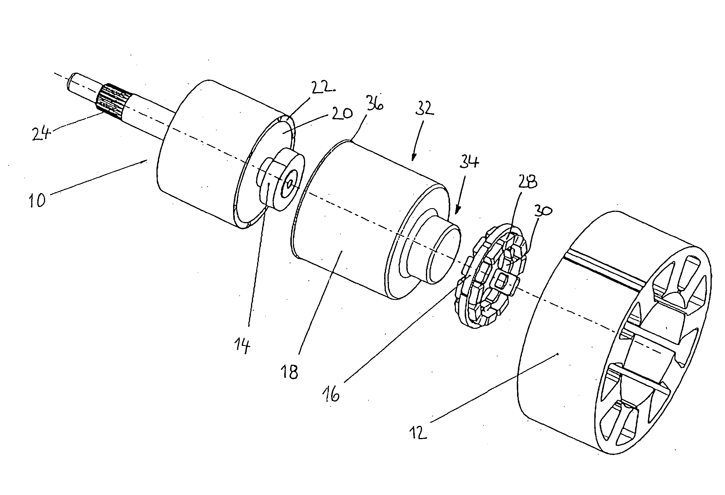
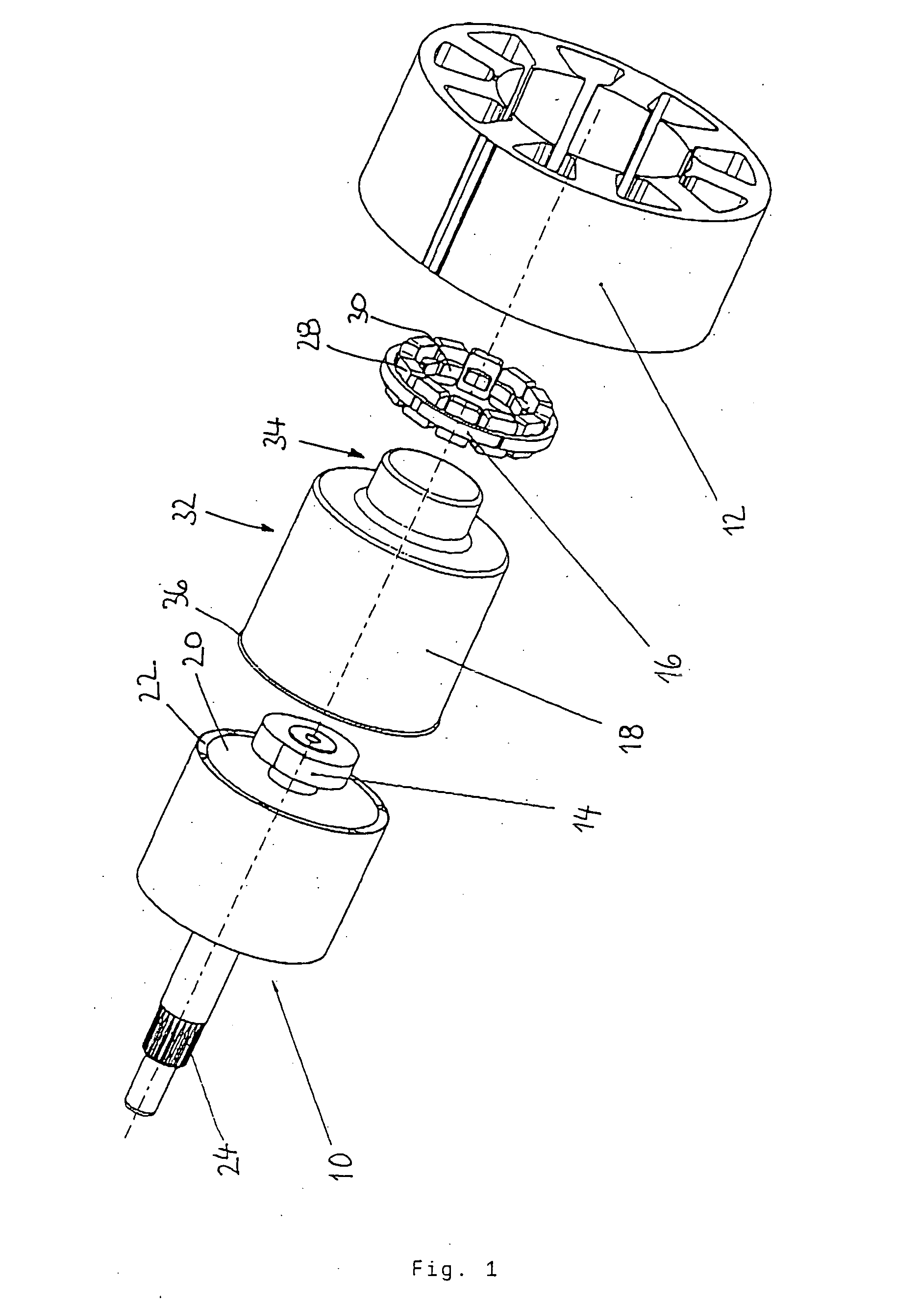
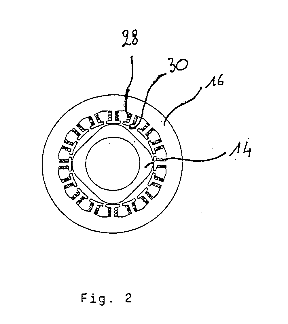
[0027] The canned motor according to the invention illustrated in the figure, includes a rotor 10, a stator 12, a resolver having a resolver rotor 14 and a resolver stator 16, and a can 18.

[0028] The rotor 10 includes a back iron yoke 20, a permanent magnet 22 and a rotor shaft 24. The stator 12 is shown only schematically by a stator core 26 having nine stator poles, the windings not being shown for the sake of clarity.

[0029] The resolver rotor 14 is seated on one end of the rotor shaft 24 lying opposite to the drive end. The resolver rotor 14 rotates with th...


PUM


Abstract

The canned motor in accordance with the invention comprises a rotor having a rotor shaft; a can having a cylindrical wall which is closed at one end; and a stator, the cylindrical wall of the can being inserted between the rotor and the stator. To measure the rotational position and, where applicable, the number of revolutions of the rotor, the invention provides a resolver integrated in the canned motor which has a resolver rotor that rotates with the rotor and a stationary resolver stator, the cylindrical wall of the can also lying between the resolver rotor and the resolver stator. The resolver enables the rotational position of the rotor, in particular, to be precisely measured as well as the number of revolutions, and thereby enables the motor to be regulated as basically known from the field of electronically commutated DC motors.

Description

FIELD OF THE INVENTION [0001] The invention relates to a canned motor in accordance with the preamble of patent claim 1. Such a canned motor is known for example from EP 0 846 365 B1. BACKGROUND OF THE INVENTION [0002] To pump aggressive liquids, for example, or water of the highest purity, a complete separation between the drive motor and the pump is required. For such applications, it is known to use a canned motor or gap tube motor which has a tube arranged in the gap between the stator and the rotor. It is also known to suspend the rotor in the gap tube hydrostatically or by means of a sliding bearing. Canned motors have the advantage that the electrical drive side can be hermetically separated by the gap tube or can from the rotating parts and the forwarded medium. Depending on the design of the bearing, the can may be operated for both wet running and dry running. In designing a canned motor it is always important to ensure that the gap tube is sufficiently stable so that the ...

Claims


Application Information

Patent Timeline
Patent Type & Authority Applications(United States)
IPC IPC(8): H02K5/128H02K11/00H02K24/00H02K29/12H02K29/14
CPCH02K5/128H02K29/14H02K29/12H02K24/00
Inventor RITZINGER, CHRISTIANENGESSER, MARTINSEMMA, KURT
Owner MINEBEAMITSUMI INC
Why Eureka
Try Eureka