Bi-level coupler

a coupler and bi-level technology, applied in the direction of waveguides, impedence networks, snap-action arrangements, etc., can solve the problems of very tight coupling of the center section, very long coupling, loss,

Active Publication Date: 2005-06-09
WERLATONE INC
View PDF35 Cites 31 Cited by
  • Summary
  • Abstract
  • Description
  • Claims
  • Application Information

AI Technical Summary

Benefits of technology

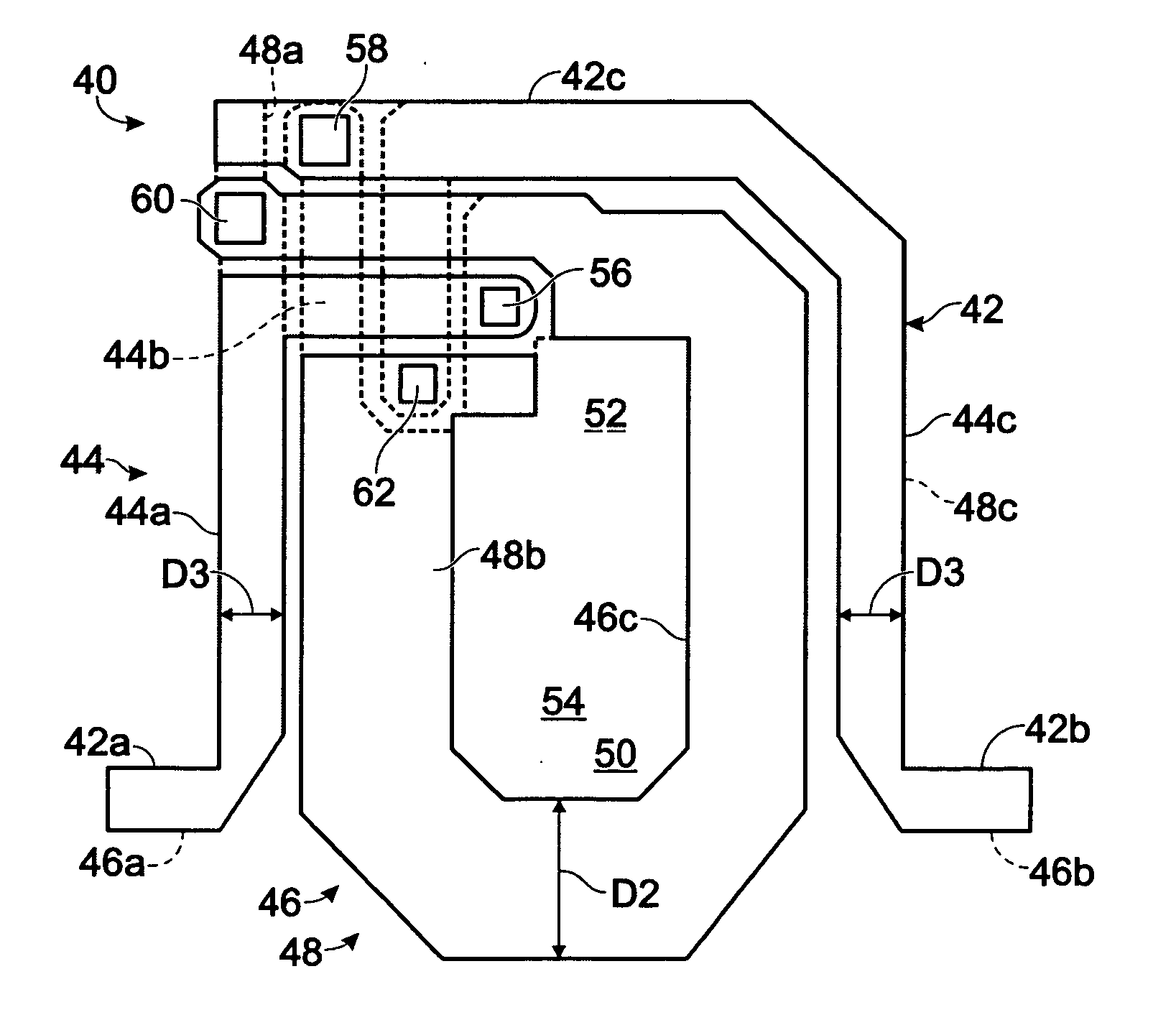
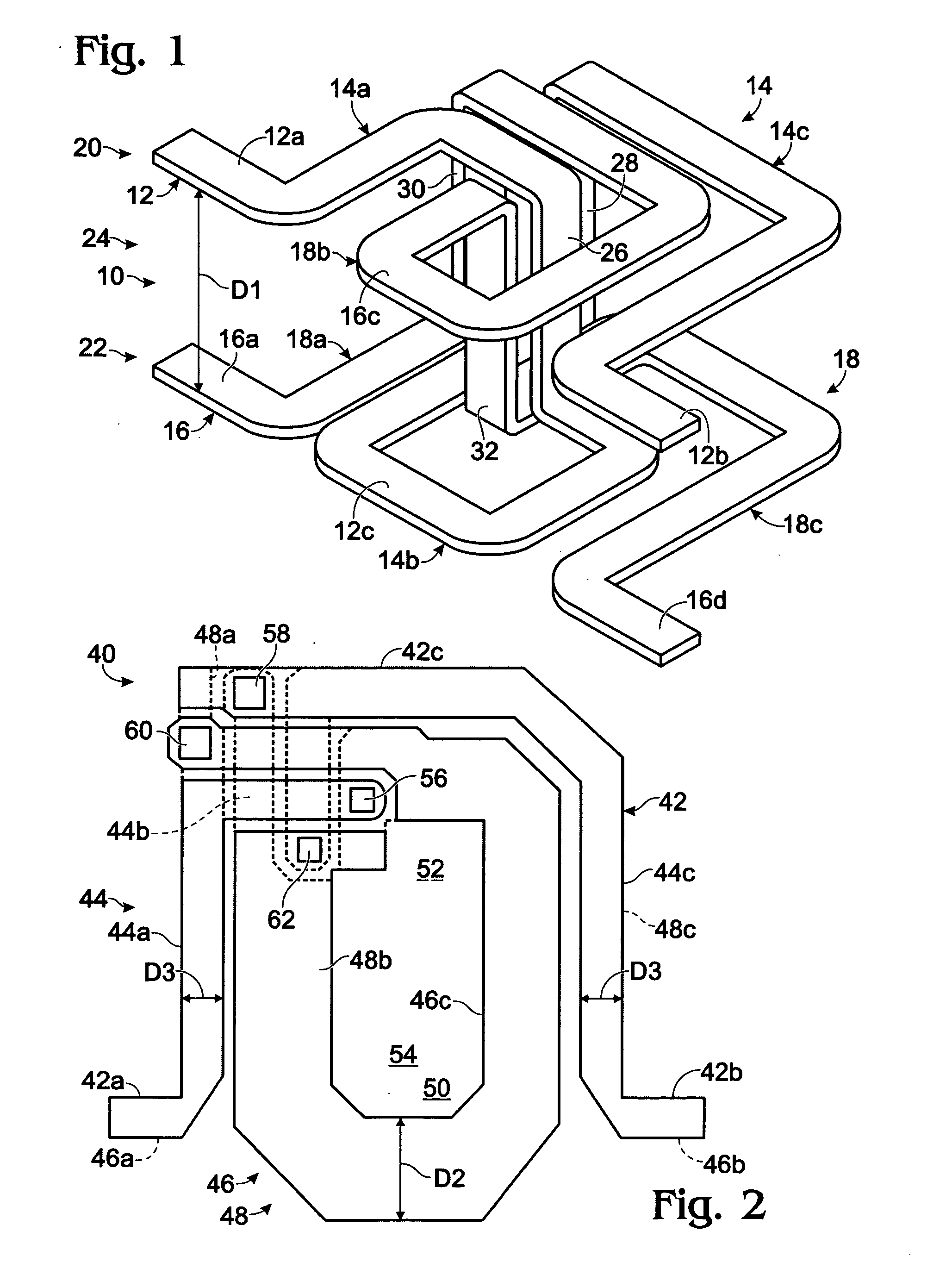
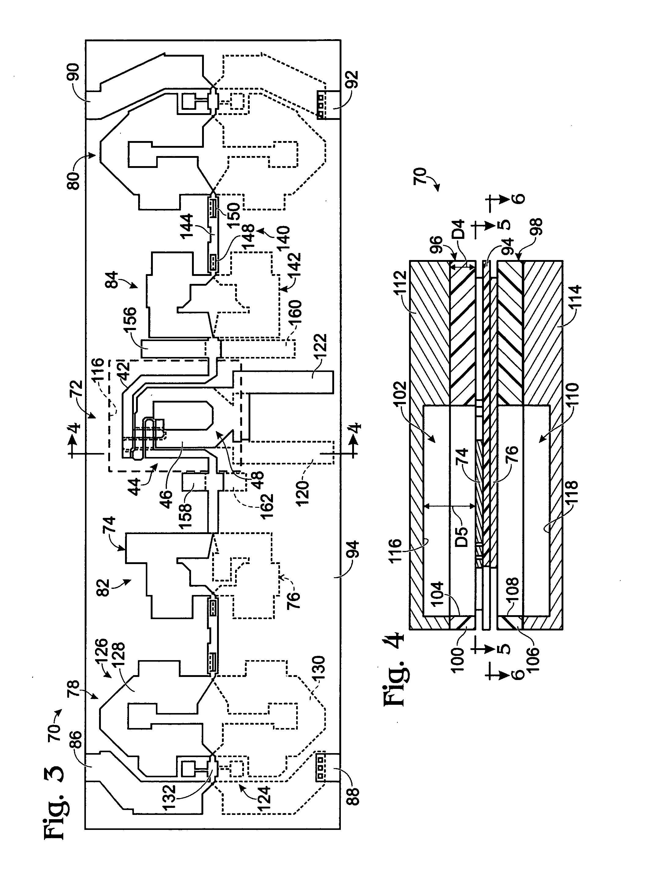
[0008] A coupler is disclosed that includes first and second mutually coupled spirals disposed on opposite sides of a dielectric substrate. The substrate may be formed of one or more layers and the coils may hav

Problems solved by technology

One is that the coupler becomes very long and lossy, since its combined length is more than one-quarter wavelength long at

Method used


Image

  • Bi-level coupler
  • Bi-level coupler
  • Bi-level coupler

Examples


Embodiment Construction

[0017] Two coupled lines may be analyzed based on odd and even modes of propagation. For a pair of identical lines, the even mode exists with equal voltages applied to the inputs of the lines, and for the odd mode, equal out-of-phase voltages this model may be extended to non-identical lines, and to multiple coupled lines. For high directivity in a 50-ohm system, for example, the product of the characteristic impedances of the odd and even modes, e.g., Zoe*Zoo is equal to Zo2, or 2500 ohms. Zo, Zoe, and Zoo are the characteristic impedances of the coupler, the even mode and the odd mode, respectively. Moreover, the more equal the velocity of propagation of the two modes are, the better the directivity of the coupler.

[0018] A dielectric above and below the coupled lines may reduce the even-mode impedance while it may have little effect on the odd mode. Air as a dielectric, having a dielectric constant of 1, may reduce the amount that the even-mode impedance is reduced compared to ot...


PUM


Abstract

A coupler is disclosed that includes first and second mutually coupled spirals disposed On opposite sides of a dielectric substrate. The substrate may be formed of one or more layers and the coils may have a number of turns appropriate for a given application. Conductors forming the spirals may be opposite each other on the substrate and each spiral may include one or more portions on each side of the substrate. Each conductor of the coupler may include an intermediate portion having a width that is more than the width of end portions. An extension may extend from each respective intermediate portion, with the two extensions extending in non-overlapping relationship.

Description

BACKGROUND [0001] A pair of conductive lines are coupled when they are spaced apart, but spaced closely enough together for energy flowing in one to be induced in the other. The amount of energy flowing between the lines is related to the dielectric medium the conductors are in and the spacing between the lines. Even though electromagnetic fields surrounding the lines are theoretically infinite, lines are often referred to as being closely or tightly coupled, loosely coupled, or uncoupled, based on the relative amount of coupling. [0002] Couplers are electromagnetic devices formed to take advantage of coupled lines, and may have four ports, one associated with each end of two coupled lines. A main line has an input connected directly or indirectly to an input port. The other end is connected to the direct port. The other or auxiliary line extends between a coupled port and an isolated port. A coupler may be reversed, in which case the isolated port becomes the input port and the inp...

Claims


Application Information

Patent Timeline
IPC IPC(8): H01P5/18
CPCH01P5/187H01P5/18H01H5/16H01P5/12
Inventor PODELL, ALLEN F.
Owner WERLATONE INC
Why Eureka
Try Eureka