
Power saving wireless telemetering system

a wireless telemetering and power saving technology, applied in the field of telemetering systems, can solve problems such as the inability to update the time schedule of remote sensor modules

Inactive Publication Date: 2005-06-09
NEC CORP
View PDF3 Cites 66 Cited by
  • Summary
  • Abstract
  • Description
  • Claims
  • Application Information

AI Technical Summary

Benefits of technology

[0011] According to a fourth aspect of the present invention, there is provided a wireless sensor node for a telemetering system including a wireless base station which transmits power saving time-schedule data to a plurality of wireless sensor nodes, wherein the wireless sensor node is one of the plurality of wireless sensor nodes, the sensor node comprising a power source, a sensor for producing observation data indicating a quantity being measured, a wireless interface for receiving the observation data from the sensor when the wireless interface is activated, a tim...

Problems solved by technology

Once the telemetering system became operational, it was impossible to update the time schedule of the remote sensor modules.

Method used


Image

  • Power saving wireless telemetering system
  • Power saving wireless telemetering system
  • Power saving wireless telemetering system

Examples


Embodiment Construction

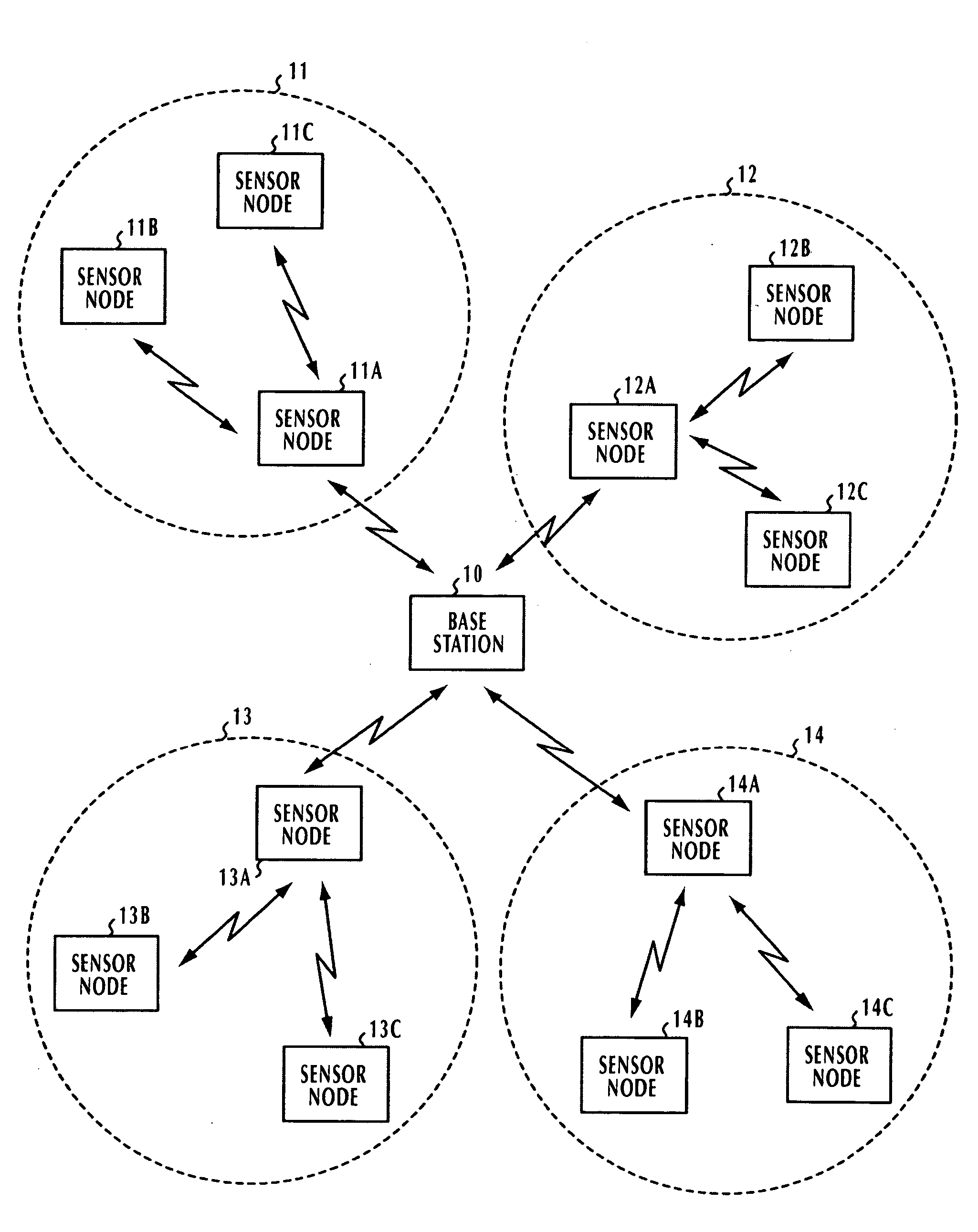
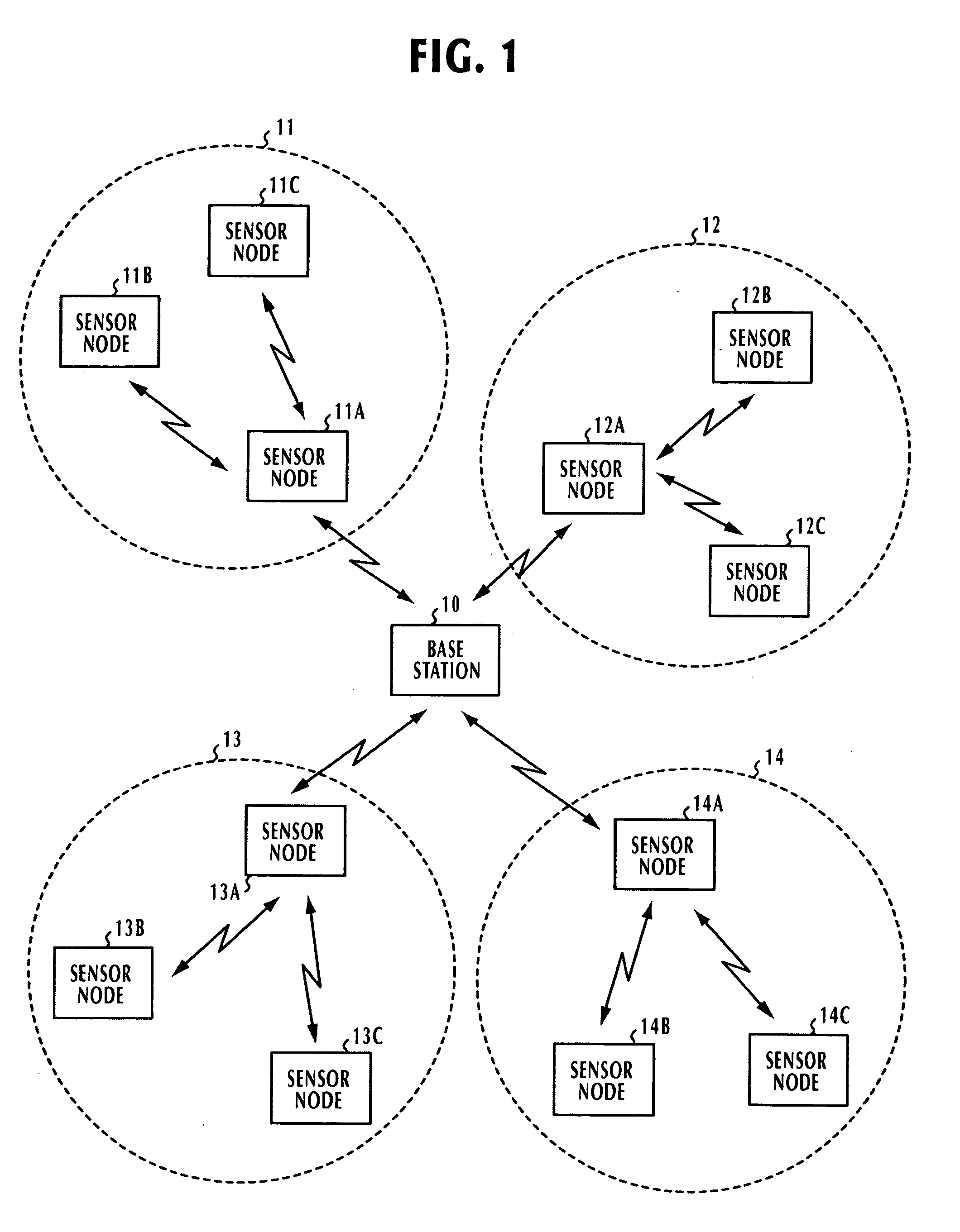
[0023] In FIG. 1, a wireless telemetering network of the present invention comprises a wireless base station or data collection center 10 and a plurality of groups 11, 12, 13 and 14 of wireless sensor nodes located at distances from the base station. The sensor nodes of each group are indicated by the letters A, B and C appended to their group number. In each of the groups 11 to 14, the sensor node A is nearest to the base station and the transmit power of the base station 10 is reachable only to these nearest sensor nodes 11A, 12A, 13A and 14A. Therefore, the base station 10 operates as an upstream node in the direction of its packet transmission, and in each group, the sensor node A operates as a repeater node for repeating the packet to the other nodes, or downstream nodes B and C. Likewise, in the opposite direction of transmission, the sensor node A repeats packets from the nodes B and C to the base station 10.

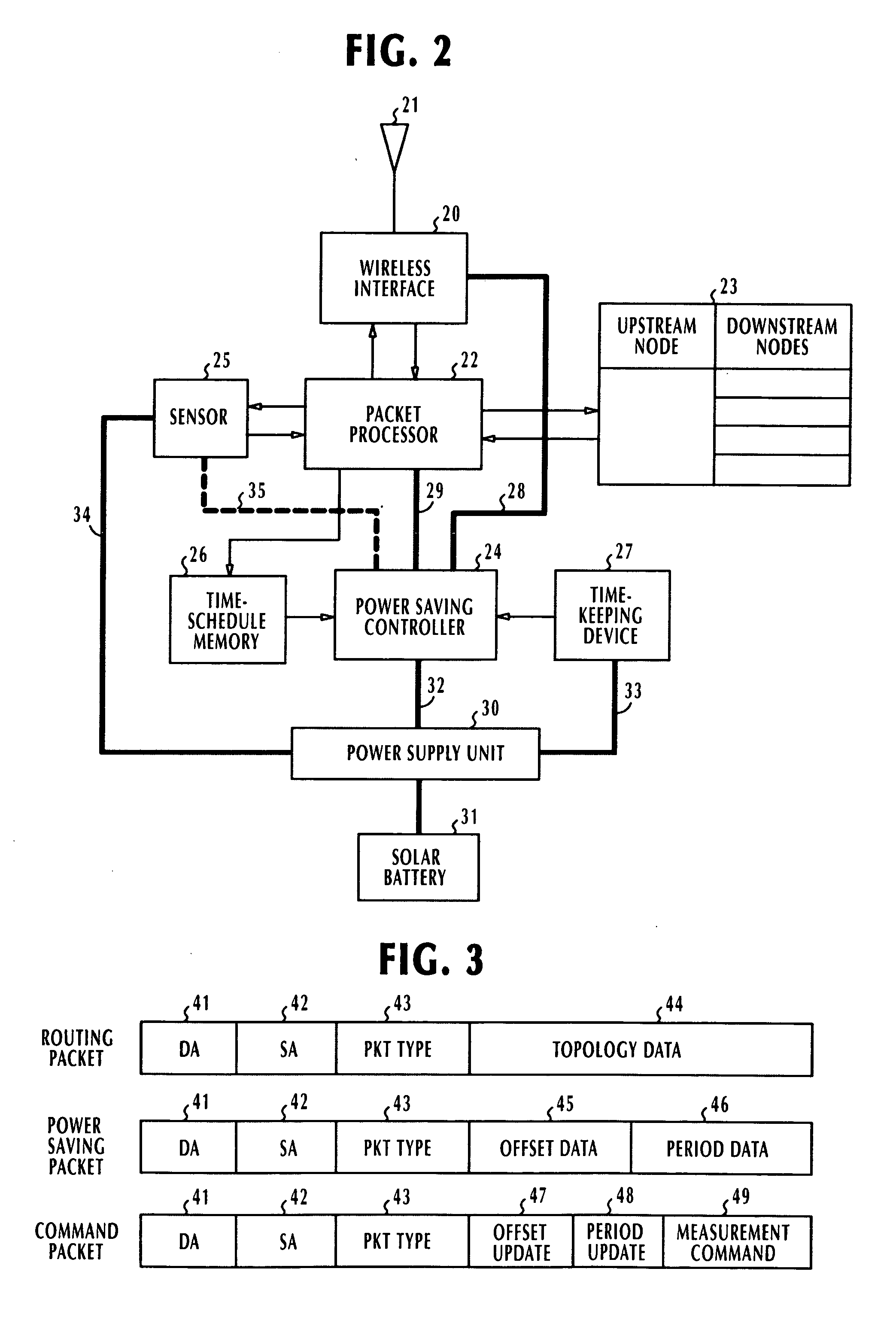
[0024] As shown in detail in FIG. 2, each of the wireless sensor no...


PUM


Abstract

Disclosed is a telemetering system that comprises a wireless base station and a number of wireless sensor nodes. Each wireless sensor node includes a solar cell, a sensor for producing observation data indicating a quantity being measured, a wireless interface for receiving the observation data from the sensor when the node is activated, and a time-schedule memory for storing time-schedule data. Control circuitry briefly activates its own node by supplying power from the solar cell to the wireless interface at periodic intervals according to the time-schedule data of the memory and briefly establishes a wireless link to the base station. During the time the wireless link is briefly established, the control circuitry of each node transmits the observation data to the base station and updates its time-schedule memory if it receives time-schedule data from the base station.

Description

BACKGROUND OF THE INVENTION [0001] 1. Field of the Invention [0002] The present invention relates generally to telemetering systems, and more specifically to a wireless telemetering system in which observation data are wirelessly collected at a central location from remote wireless sensor at periodic intervals for power saving purposes. [0003] 2. Description of the Related Art [0004] A known telemetering system comprises a plurality of wireless modules to perform measurement of physical quantities at remote locations. For power saving purposes, each sensor module is provided with a time-keeping device and the current time supplied from the device is constantly compared to power saving time-schedule. When the current time of day coincides with each successive instant of the time schedule, the sensor module is activated briefly and transmits a signal indicating a quantity being measured. Since the prior art sensor modules were designed to meet strict specifications that they must be o...

Claims


Application Information

Patent Timeline
IPC IPC(8): H04B1/16H04Q9/00G08C17/00
CPCH04Q9/00H04W52/0216H04W52/0248H04Q2209/883H04Q2209/40H04Q2209/886Y02B60/50Y02D30/70
Inventor ISOYAMA, KAZUHIKOOHKUMA, TAKAHIROKAWASAKI, DAISUKE
Owner NEC CORP
Learn More