Input pen and input device

a technology which is applied in the field of input pen and input device, can solve the problem of drawing expressed with a given line width

Inactive Publication Date: 2005-06-09
FUJITSU COMPONENENT LTD
View PDF5 Cites 138 Cited by
  • Summary
  • Abstract
  • Description
  • Claims
  • Application Information

AI Technical Summary

Benefits of technology

[0025] According to yet another aspect of the present invention, there is provided an input device includes an input pen and a receiver, and the input pen in use for an input device includes a first member, a second member that moves together with a pen tip, a touch area between the first member and the second member being variable, and a pen pressure detecting circuit that detects an amount of the pen pressure that is applied to the pen tip, based on the touch area. It is thus possible to provide the input device that is able to detect the amount of the pen pressure and thereby possible to express the different line widths according to the amount of the pen pressure.

Problems solved by technology

There is the drawback in that a drawing is expressed with a given line width only.

Method used


Image

  • Input pen and input device
  • Input pen and input device
  • Input pen and input device

Examples


first embodiment

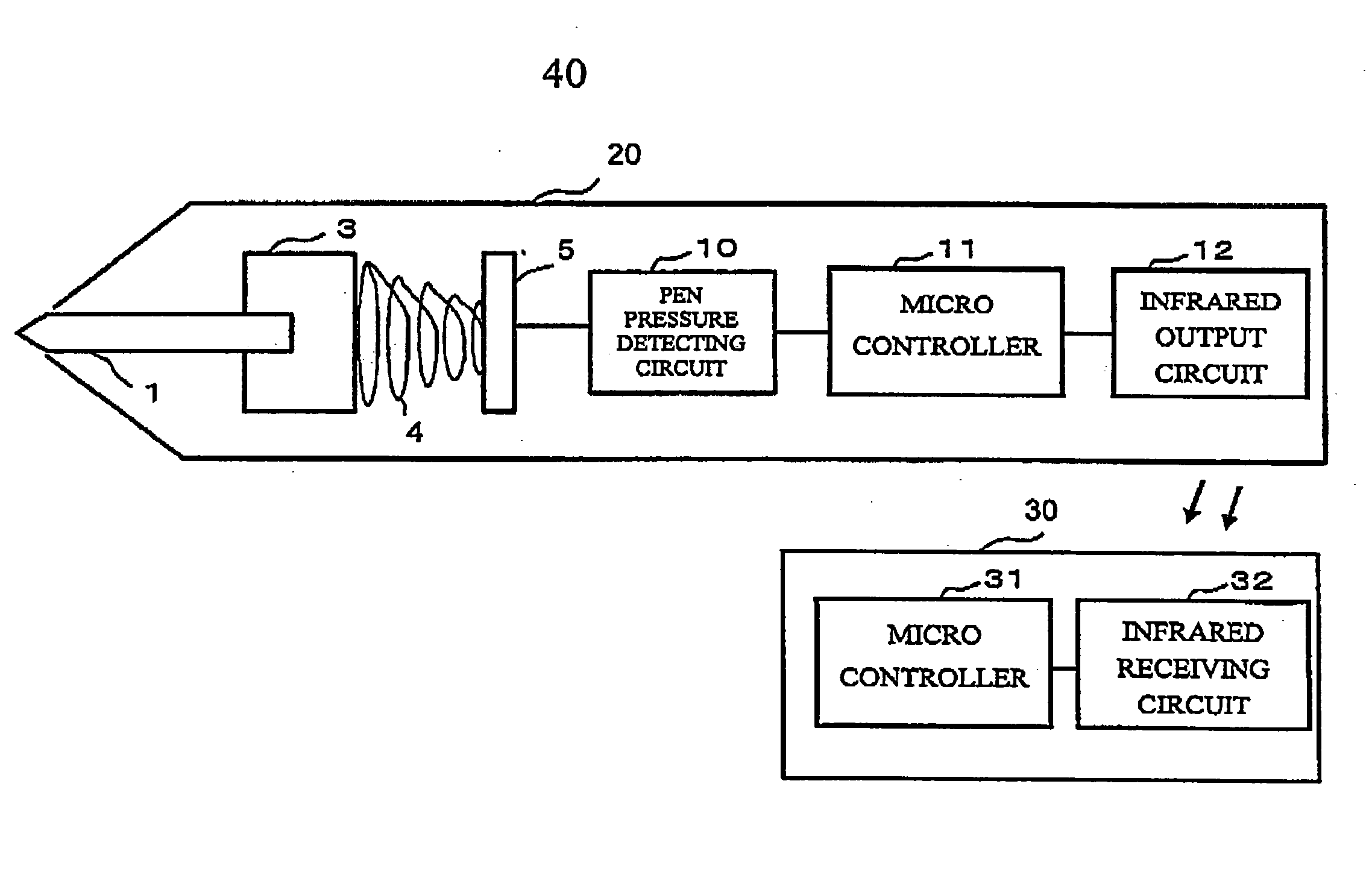
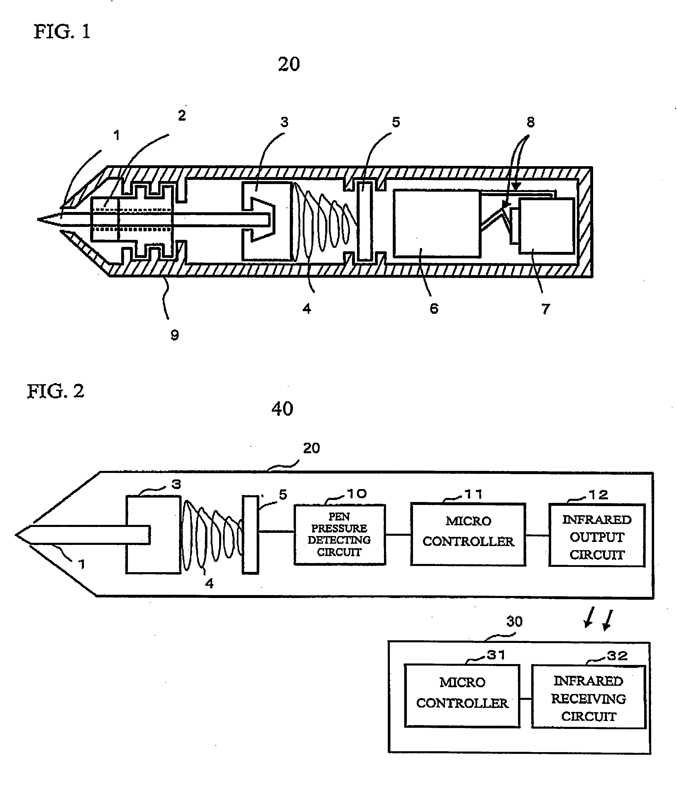
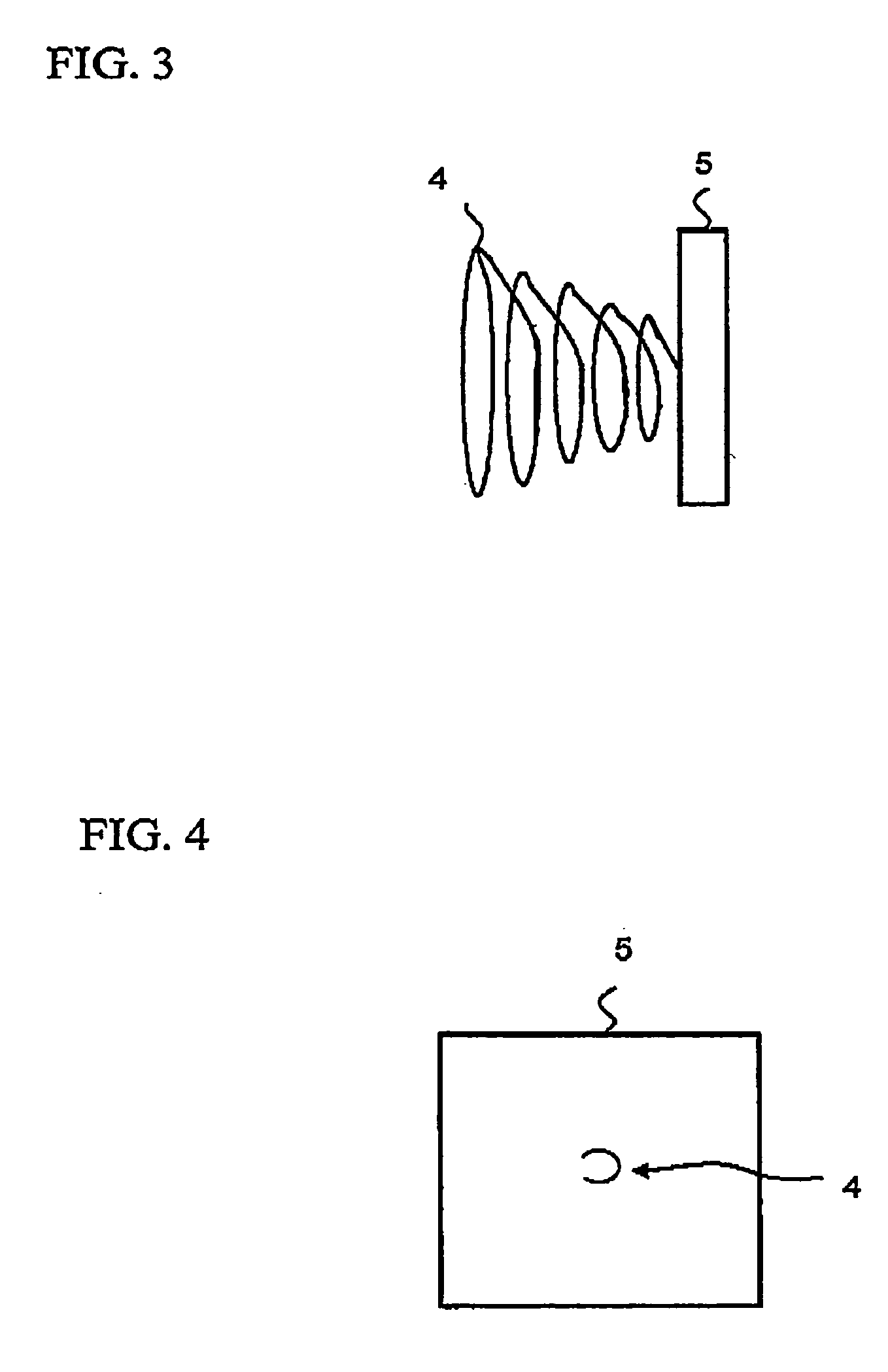
[0049]FIG. 1 is a cross-sectional view of an input pen of an input device in accordance with a first embodiment of the present invention. FIG. 2 is a block diagram of the input device in accordance with the first embodiment of the present invention. Referring to FIG. 2, an input device 40 includes an input pen 20 and a receiver 30. Referring to FIG. 1, the input pen 20 includes a pen tip 1, an ultrasonic sensor 2, a pen tip holder 3, a spring 4, a resistance film 5, a circuit board 6, a battery 7, electrodes for battery 8, and a case 9. As shown in FIG. 2, the input pen 20 includes the pen tip 1, the pen tip holder 3, the spring 4, the resistance film 5, a pen pressure detecting circuit 10 that detects the pen pressure, a microcontroller 11, and an infrared output circuit 12.

[0050] The input pen 20 has a shape of a pen, and serves as a transmitter that transmits the pen pressure information to the receiver 30. The pen tip 1 is held by the pen tip holder 3. The ultrasonic sensor 2 s...

second embodiment

[0067] Next, a description will be given of a second embodiment of the present invention. FIG. 12 is a circuit diagram of a pen pressure detecting circuit 110 in accordance with the second embodiment of the present invention. The pen pressure detecting circuit 10 in accordance with the first embodiment of the present invention determines the pen pressure applied to the pen tip with the three comparators 101 through 103. The pen pressure detecting circuit 110 in accordance with the second embodiment of the present invention, however, employs an A / D converter 111 instead of the comparators so as to convert Vi that is an analog signal into a digital signal and indicate the pen pressure information. This makes it possible to determine the amount of the pen pressure in more detail than the pen pressure detecting circuit 10 in accordance with the first embodiment of the present invention. FIGS. 13A through 13C show infrared output patterns of the infrared output circuit 12 in accordance w...

third embodiment

[0070] Next, a description will be given of a third embodiment of the present invention. The spring, which shrinks or elongates according to the pen pressure, has been described above. Rubber is employed instead of the spring in accordance with the third embodiment of the present invention. FIG. 14 shows an input pen 120 in accordance with the third embodiment of the present invention. Referring to FIG. 14, the input pen 120 includes the pen tip 1, the pen tip holder 3, a conductive rubber 41, the resistance film 5, the pen pressure detecting circuit 10, the microcontroller 11, and the infrared output circuit 12. Hereinafter, in the third embodiment, the same components and configurations as those of the first and second embodiments have the same reference numerals and a detailed explanation will be omitted.

[0071] The rubber 41 is an elastic material, and is arranged between the pen tip holder 3 and the resistance film 5. The resistance value of the resistance film 5 varies accordi...


PUM


Abstract

An input device includes an input pen that is capable of detecting an amount of a pen pressure applied to a pen tip. The input pen has a resistance film that alters a resistance vale thereof according to a touch area, a spring that alters the touch area between the spring and the resistance film, a pen pressure detecting circuit that detects the amount of the pen pressure applied to the pen tip based on the touch area, and an infrared output circuit that outputs the amount of the pen pressure to a receiver with the use of infrared rays. The spiral-shaped spring is configured so that a diameter may become smaller as further from the pen tip. It is thus possible to detect the amount of the pen pressure applied to the pen tip based on the touch area that varies according to a movement of the pen tip, and thereby possible to express different line widths in drawing according to the amount of the pen pressure applied to the pen tip.

Description

BACKGROUND OF THE INVENTION [0001] 1. Field of the Invention [0002] This invention generally relates to an input pen and input device. [0003] 2. Description of the Related Art [0004] A conventional pen-type coordinate input device does not include a function of detecting a pen pressure on a transmitter, in the case where the conventional input device employs another method rather than a tablet method, which utilizes electromagnetic waves, for example, an ultrasonic method. Therefore, the transmitter was able to transmit only two types of information to a receiver, writing or not writing. [0005] Accordingly, it was impossible to change a line width in drawing depending on the pen pressure sensed by the transmitter, with an application software on a host machine that is connected to the receiver. There is the drawback in that a drawing is expressed with a given line width only. The techniques have been proposed by Japanese Patent Application No. 7-261906 (hereinafter referred to as Do...

Claims


Application Information

Patent Timeline
Patent Type & Authority Applications(United States)
IPC IPC(8): G06F3/033G09G5/00
CPCG06F3/03545
Inventor SAKURAI, SATOSHIYATSU, NOBUOHARADA, KEITA
Owner FUJITSU COMPONENENT LTD
Why Eureka
Try Eureka