User-interface and method for curved multi-planar reformatting of three-dimensional volume data sets
Active Publication Date: 2005-06-09
TOSHIBA MEDICAL VISUALIZATION SYST EURO
View PDF1 Cites 58 Cited by
Summary
Abstract
Description
Claims
Application Information
AI Technical Summary
This helps you quickly interpret patents by identifying the three key elements:
Problems solved by technology
Method used
Benefits of technology
Benefits of technology
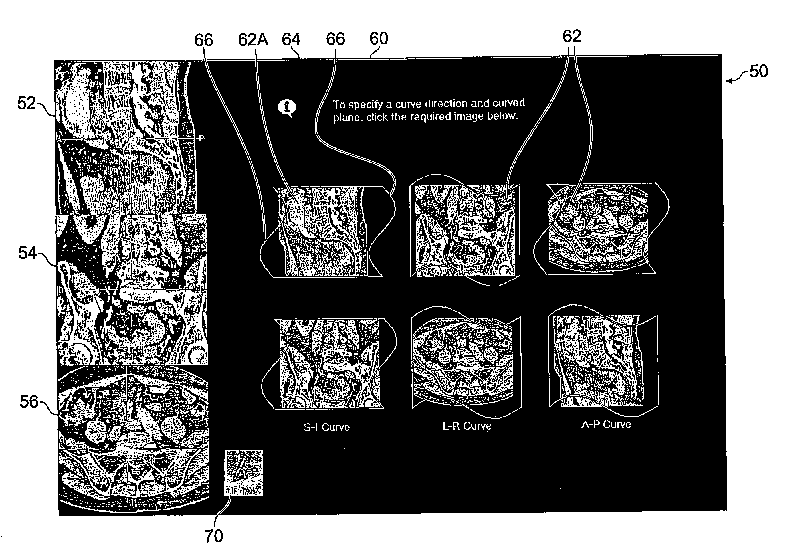
[0019] In one embodiment, the plurality of selectable icons comprises six icons each representing one of six possible combinations of a plane parallel to one of the orthogonal MPR images and a direction substantially normal to a plane parallel to one of the other two MPR images, the six icons being individually selectable to allow the user to select both a direction to be taken by the curve, and a plane parallel to one of the MPR images. In this case, the curve-related MPR image shown in the fourth display area may be a curved MPR image having a view direction substantially normal to the selected plane. Six separate icons bearing this information covers every combination of pairs of orthogonal directions, so allows the user full, simple and intuitive access to every possible curve orientation which can be specified for curved MPR images.
[0020] In an alternative embodiment, the plurality of selectable icons comprises six icons each representing one of six possible combinations of a plane parallel to one of the orthogonal MPR images and a direction substantially normal to a plane parallel to one of the other two MPR images, the six icons being grouped in selectable pairs, each pair having a common direction to be taken by the curve, to allow the user to select a direction to be taken by the curve. In this case, the curve-related MPR image shown in the fourth display area may be a cross-curve MPR image showing an image perpendicular to the curve at a selected position. Once again, the icons are a simple way of specifying the desired orientation. Although a choice of one from three directions is all that is required for cross-curve MPR, the use of six icons as coupled pairs allows the same icons and icon configuration to be used for both the cross-curve and the curved embodiments. This simplifies the interface as regards data and processing requirements, and also increases ease of use because the user only has to become familiar with one interface to be able to use both MPR techniques.
[0021] In addition, after the curve has been defined, the selected pair of icons can be redisplayed in the fourth display area as individually selectable icons to allow the user to select a plane parallel to one of the MPR images, and after selection the fourth display area shows a curved MPR image having a view direction substantially normal to the selected plane. This configuration gives great flexibility to the MPR process, because the user can readily specify the extra information needed for curved MPR, and vie
Problems solved by technology
This is in contrast with previous MPR systems in which user input is less and assumptions are necessary, which can generate confusing images with orientations which are difficult to determine.
In some c
Method used
Image
Click on the blue label to locate the original text in one second.
Reading with bidirectional positioning of images and text.
Examples
first embodiment
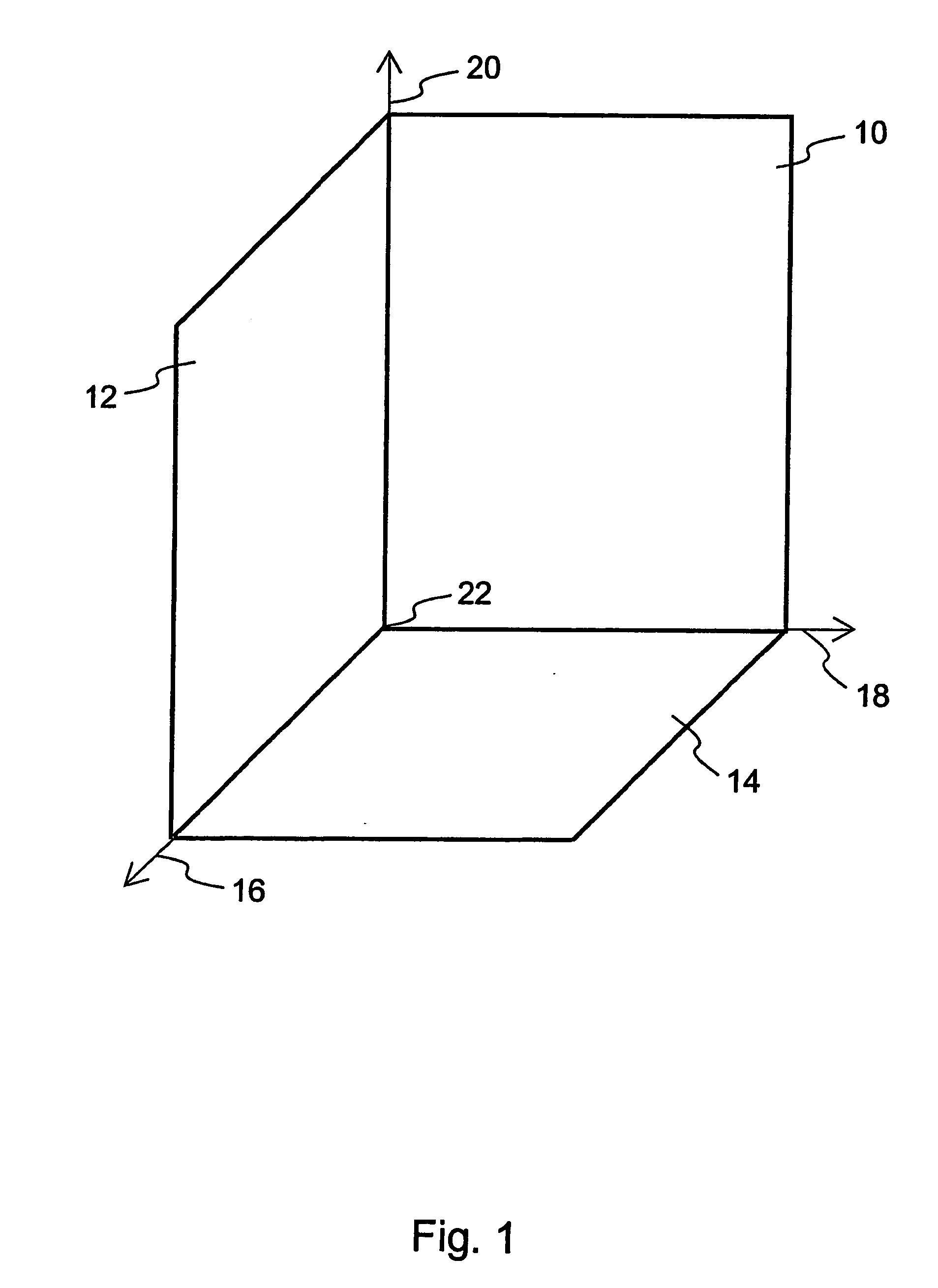
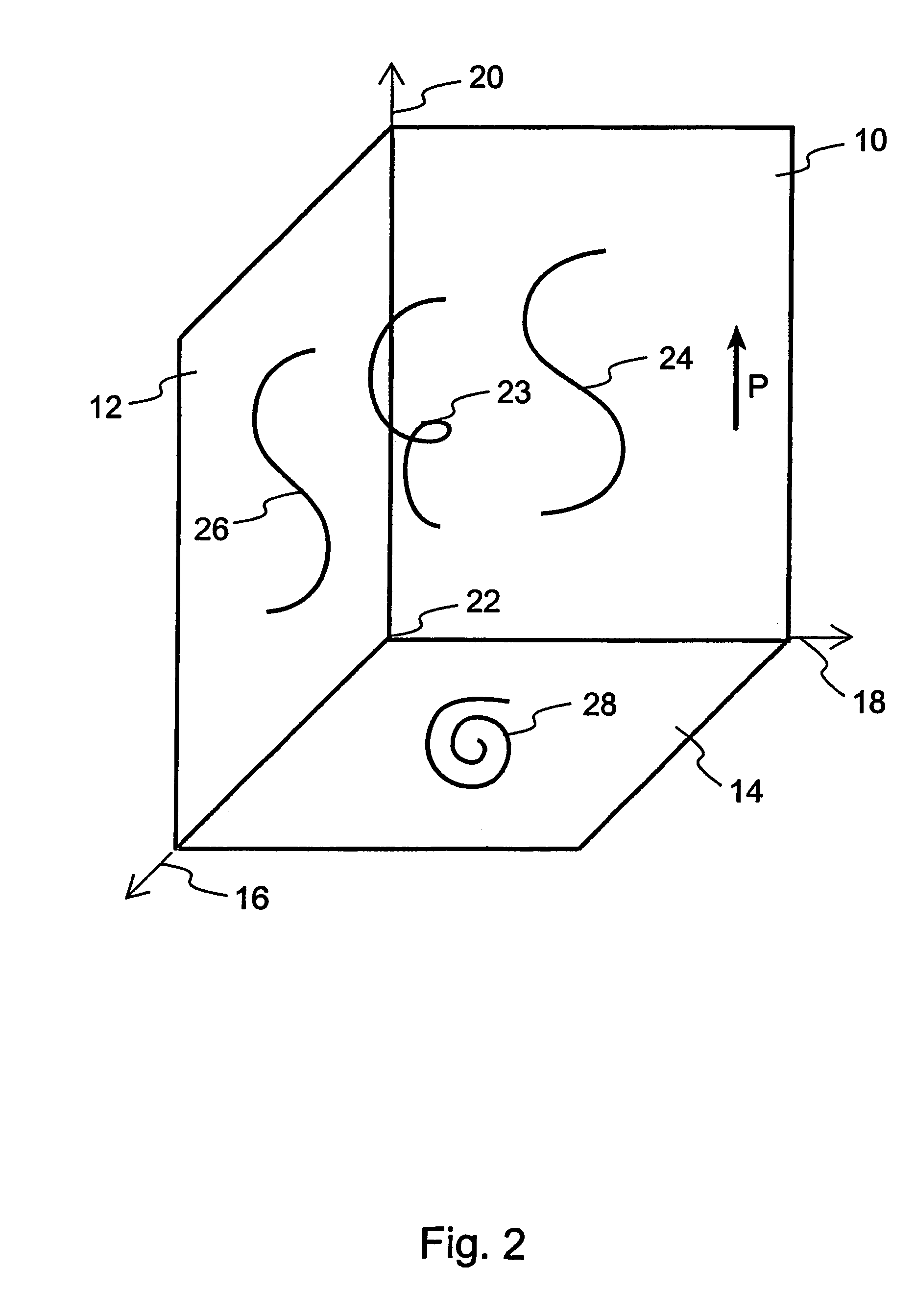
[0081] As is evident from the foregoing description of curved MPR, there are many variables which affect the final curved MPR image displayed to the viewer. These include the shape of the curve, the tracking MPR plane, the primary direction of the curve, the MPR plane “to be curved”, and the extrusion direction. The embodiments of the present invention seek to provide the user with as much flexibility in selecting and modifying these variables as possible while maintaining an easy-to-understand user interface. This allows the user to be confident that the final curved MPR image depicts the relevant parts of the patient, so that accurate clinical decisions can be based thereon.
[0082] Thus the present invention is concerned with the user interface of a computer implemented curved MPR image processing package. It provides the user with the ability to make a range of choices, and to modify the choices after generation of the MPR image. This is in contrast with prior art systems, which ...
second embodiment
[0099] The user interface of the first embodiment can be modified for display of cross-curve MPR views. To generate a cross-curve MPR view, it is only necessary to specify the primary direction of the curve. There is no “curving” carried out, so there is no need to select a MPR view “to be curved”. Consequently, there are only three possible options to choose between, instead of the six required for a curved MPR view.
[0100] Each of the three choices are of the form “the primary direction of the curve is along the Foo axis—i.e. the Foo MPR is the tracking MPR”, where Foo is a standard axis. The choice is expressed as “Create a Foo curve”. The choices therefore are: [0101] Create a Transverse curve [0102] Create a Coronal curve [0103] Create a Sagittal curve
[0104] In the second embodiment, each choice is represented by a pair of icons, showing the two non-Foo MPR views adorned with a generic curved line or lines to represent the Foo curve. Thus six icons are again provided, and may ...
third embodiment
[0107] A user interface for cross-curve MPR can alternatively have three icons instead of six icons linked in pairs, since the choice of the user is limited to the selection of one of three directions for the curve. Hence one selectable icon is provided on the interface for each of the three directions. Once again, thumbnail versions of the standard planar MPR images can be used. However, in this embodiment, the thumbnail shows the tracking MPR plane, instead of the MPR plane which is to be curved. There is no requirement for any curved lines to be overlaid on the icons, because the MPR images shown are not going to be curved, and the curve itself is going to be roughly normal to the image. Thus the information suggested by the curved lines of the first and second embodiments is not relevant.
[0108]FIG. 7(b) shows a user interface 200 with icons of this type. As before, the user interface 200 has first, second and third display areas 202, 204, 206 in which are displayed three orthog...
PUM
Abstract
A user interface for a computer-implemented Multi-Planar Reformatting (MPR) system comprises three display areas in which are displayed three orthogonal MPR images of the volume data set; a curve drawing tool to allow a user to define a curve through the volume data set; six selectable icons each representing one of six possible combinations of a plane parallel to one of the orthogonal MPR images and a direction substantially normal to a plane parallel to one of the other two MPR images, using which the user selects an approximate direction for the curve; and a fourth display area displaying a curve-related MPR image related to one or more points along the curve. The icons may be individually selectable to allow user input of adequate orientational information for a curved MPR image, or selectable in pairs for input of directional information for a cross-curve MPR image. Alternatively, three icons may be provided for a cross-curve MPR system. A tool to allow rotation of a curved MPR image about the curve can be provided, as can visual indicators of the depth of the curve within the volume, and of the orientation of the cross-curve image.
Description
BACKGROUND OF THE INVENTION [0001] The present invention relates to curved multi-planar reformatting of three-dimensional volume data sets, particularly volume data sets representing patient images, and user interfaces for computer-implemented curved multi-planar reformatting systems. [0002] Modern patient imaging methods, such as computed tomography (CT) and magnetic resonance imaging (MRI), generate large three-dimensional volume data sets representing the patient's body. These volume data sets are highly detailed and allow complex studies of the body to be made. However, a typical volume data set will contain details of many body parts which are not relevant for a particular study, or which obscure important features. Data processing methods are hence used to manipulate the data set and present a viewer with an image which shows the items of interest in a useful and meaningful manner. [0003] The images are of necessity two-dimensional renderings of parts of the three-dimensional ...
Claims
Application Information
Patent Timeline
Application Date:The date an application was filed.
Publication Date:The date a patent or application was officially published.
First Publication Date:The earliest publication date of a patent with the same application number.
Issue Date:Publication date of the patent grant document.
PCT Entry Date:The Entry date of PCT National Phase.
Estimated Expiry Date:The statutory expiry date of a patent right according to the Patent Law, and it is the longest term of protection that the patent right can achieve without the termination of the patent right due to other reasons(Term extension factor has been taken into account ).
Invalid Date:Actual expiry date is based on effective date or publication date of legal transaction data of invalid patent.

