Motor overload tripping system and method with multi-function circuit interrupter

Active Publication Date: 2005-06-09
ROCKWELL AUTOMATION TECH
View PDF1 Cites 12 Cited by
  • Summary
  • Abstract
  • Description
  • Claims
  • Application Information

AI Technical Summary

Benefits of technology

[0004] The present invention provides a novel approach to the design and implementation of power delivery and circuit protection designed to respond to such needs. The technique of the invention permits a reduction in the number of different components needed to provide control of motors of different sizes and ratings. In particular, circuit interrupting components, such as a contactor and an instantaneous trip device may be selected based upon a higher rated current (e.g.., of a larger machine), and used for smaller machines as well. Control circuitry is then configured to cause tripping or interruption of current to either the smaller or the larger motor, depending upon which motor is coupled to the device. In other words, the components may be sized for the rating of a higher rated machine, and overrated for the smaller machines. However, algorithms implemented by the control circuitry permit interruption of current to the smaller machines via the same components.

Problems solved by technology

However, algorithms implemented by the control circuitry permit interruption of current to the smaller machines via the same components.

Method used


Image

  • Motor overload tripping system and method with multi-function circuit interrupter
  • Motor overload tripping system and method with multi-function circuit interrupter
  • Motor overload tripping system and method with multi-function circuit interrupter

Examples


Embodiment Construction

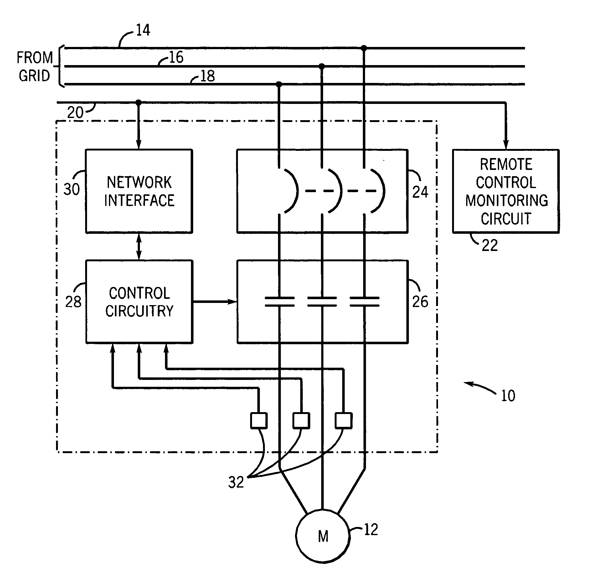
[0013] Turning now to the drawings, and referring first to FIG. 1, a protective device or system 10 is illustrated diagrammatically for providing power to and for protecting a load, such as an electric motor 12. In the illustrated embodiment, the device 10 is a three-phase device configured to deliver a three-phase power to the motor from power conductors 14, 16 and 18 which are typically coupled to the power grid. In a typical application, the protective device 10 can provide power directly from the grid to the motor, or the device may be configured for providing controlled power to the motor, such as for soft starting the motor or for driving the motor at variable frequencies (i.e. an inverter drive). Device 10 is also coupled to a network 20, such as an industrial control and monitoring network. Such networks may operate in accordance with any suitable network protocol such as well-known DeviceNet, ControlNet protocols or any other suitable protocol. As will be appreciated by tho...


PUM


Abstract

A technique is provided for controlling operation of motors of different sized or ratings. Components used to apply and interrupt current to the motors may be shared in control devices for the different motors. The components may include contactors or circuit interrupters, and instantaneous trip devices. The components may be sized for the higher rated motors, and be oversized for the lower rated motors. Control circuitry permits the devices to be controlled in accordance with the characteristics of the particular motor to which the devices are applied, providing accurate circuit interruption while reducing the number of different components and component packages in a product family for the various motors.

Description

BACKGROUND [0001] The present invention relates generally to the field of electric protective devices, such as for providing overload protection for motors and other loads. [0002] In the field of electrical protective devices, a range of devices are known and are presently in use in various combinations. For example, in a typical arrangement for applying power to a load, such as an electric motor, the circuitry may include fuses, circuit breakers, thermal overload tripping devices, contactors, and so forth. In a typical application, the components are selected and assembled based upon the current ratings and other operating parameters of the load. For example, motor protective circuitry is typically selected based upon the motor full load current rating. A thermal overload device may be selected to provide tripping at a first level, such as 6 to 10 times the full load of current rating, with faster, higher current tripping being provided by an electromagnetic device, such as a circu...

Claims


Application Information

Patent Timeline
Patent Type & Authority Applications(United States)
IPC IPC(8): H02H7/08
CPCH02H7/0833H02H3/0935
Inventor PLEMMONS, ROGER ALANBLAKELY, JOHN HERMANHELTON, GREGORY A.INNES, MARK E.HURLEY, RICKY A.
Owner ROCKWELL AUTOMATION TECH
Why Eureka
Try Eureka