Shaped wall plate for wiring device

a wiring device and wall plate technology, applied in the direction of electrical apparatus casings/cabinets/drawers, substation/switching arrangement details, casings/cabinets/drawers, etc., can solve the problem of time-consuming installation of the wall plate, misalignment and positioning problems, and operational uncertainty in the mind of the user as to which switch to use. problem, to achieve the effect of constant height increase of individual splines

Inactive Publication Date: 2005-06-09
LEVITON MFG
View PDF47 Cites 8 Cited by
  • Summary
  • Abstract
  • Description
  • Claims
  • Application Information

AI Technical Summary

Benefits of technology

[0008] The present invention discloses a wall plate which has a single opening for receiving one or a gang of two or more wiring devices. The wall plate has an opening with no dividing or separating members for receiving the one or more wiring devices and, along its vertical axis, has a surface of positive first differential and zero second differential, comprised of a combination of reference “splines” which extend between points of varying distance from a datum plane. The surface has zero secon

Problems solved by technology

In installations where there are multiple wiring devices in a common box, the installation of the wall plate can be time consuming.
Misalignment and positioning problems are often caused by wall boxes that are skewed relative to the wall or by walls which may not be flat.
The irregular in-out positioning of adjacent switches, particularly with 3-way and 4-way switches, can cause operati

Method used


Image

  • Shaped wall plate for wiring device
  • Shaped wall plate for wiring device
  • Shaped wall plate for wiring device

Examples


Embodiment Construction

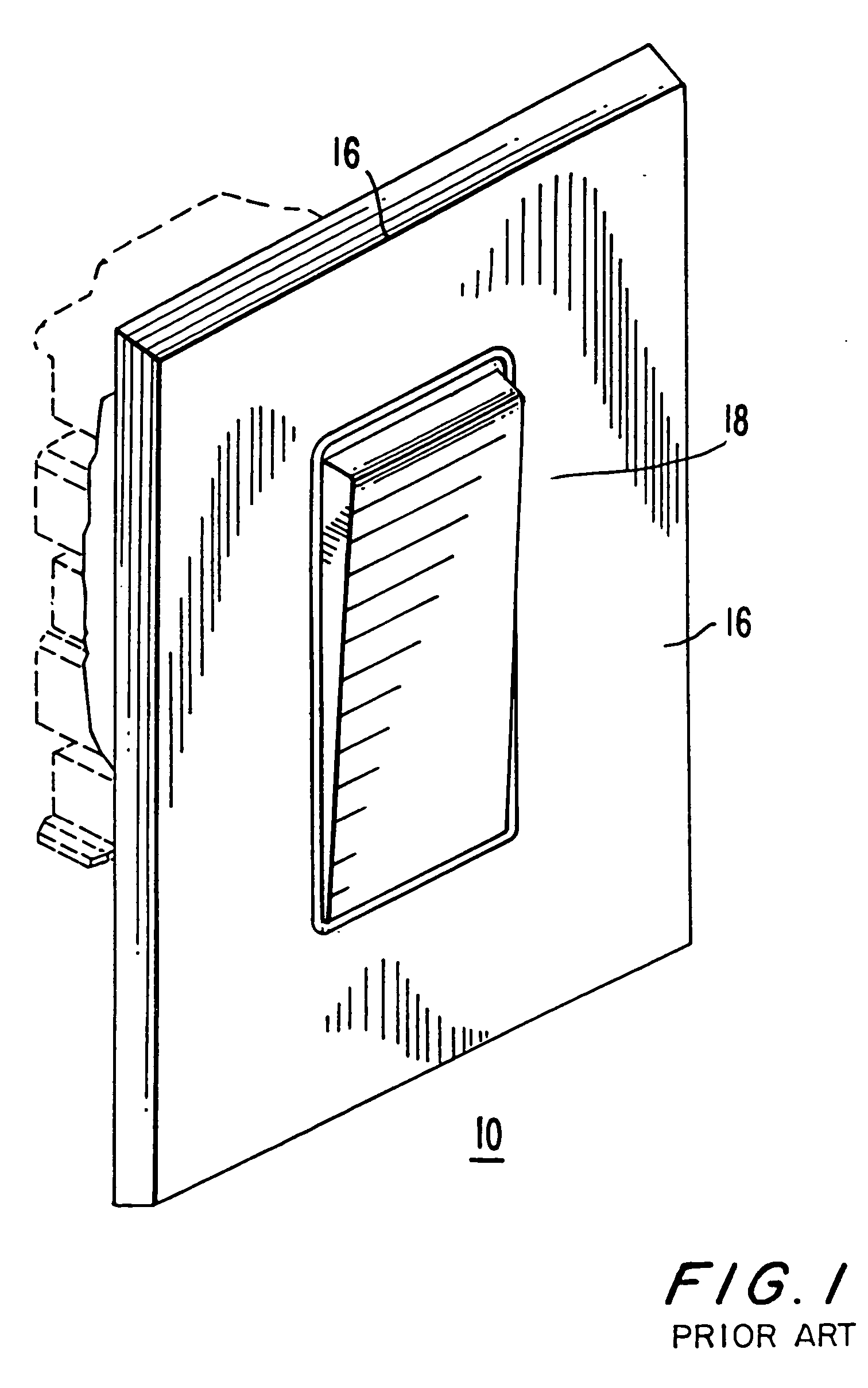
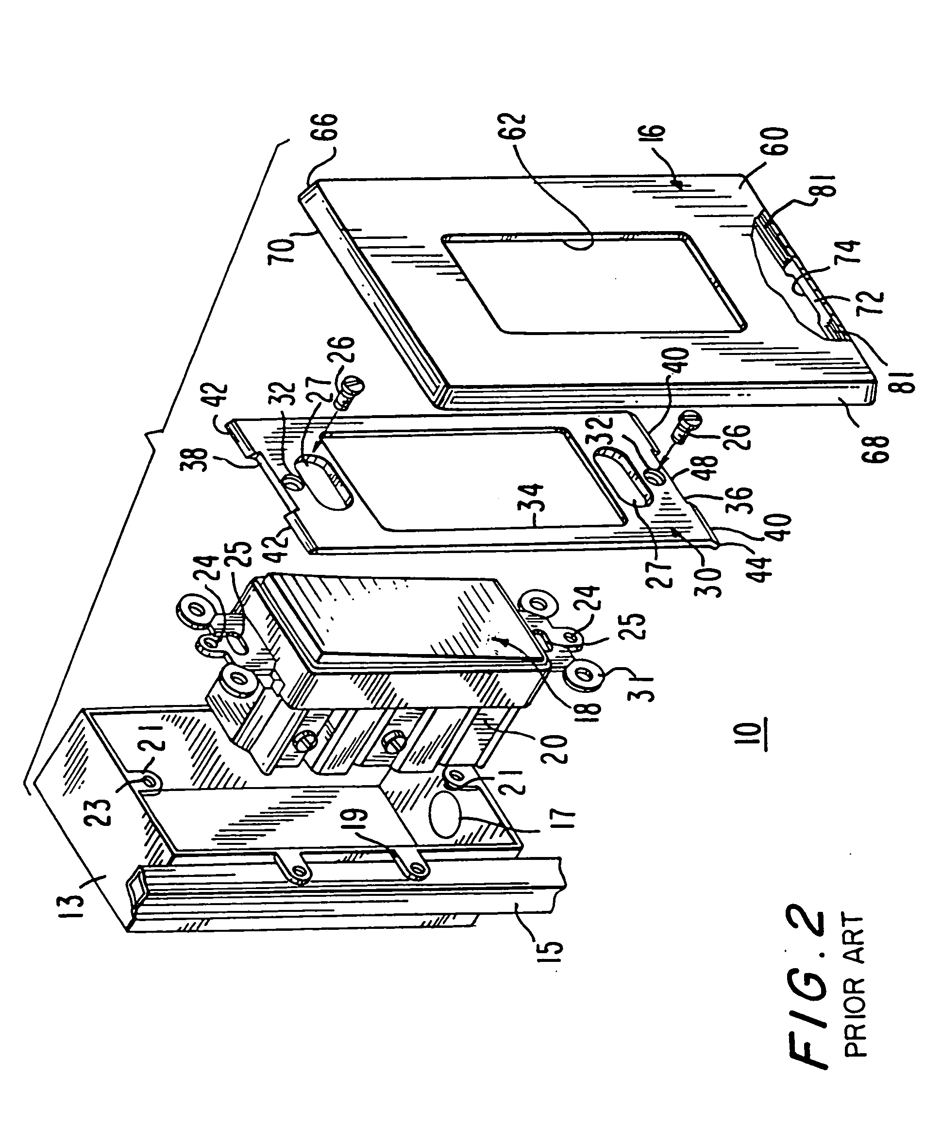
[0055] Referring to FIG. 1, there is illustrated a front perspective view of a “Decora” type electrical wall-type switch 18 and wall plate 16, as part of an assembly 10 of the prior art. Referring to FIG. 2, there is shown a perspective exploded view of the prior art device of FIG. 1 of wall box 13, electrical wiring device such as switch 18, attachment plate 30 and wall plate 16. A suitable aperture is cut into a wall to provide access for the box 13 for mounting to a stud 15, or to permit installation of a suitable box to an adjacent stud or directly to the material of the wall (such as plasterboard). The box 13 is chosen to be large enough to accept as many wiring devices as are to be mounted therein. The box 13 is made of metal or plastic, depending upon local Code requirements, and has one or more openings in its sides or back to permit the introduction of electrical wiring or cables into the interior of the box 13. Box 13 has mounting means 19 to permit the box to be anchored ...


PUM


Abstract

There is disclosed a wall plate for a wiring device. The wall plate has a single opening for receiving one or a gang of two or more wiring devices within the single opening. The wall plate has along its vertical axis, a surface of positive first differential and zero second differential, comprised of a combination of splines drawn between points of varying distance from a datum plane. The surface has zero second differential when the rate of height increase of individual splines is constant. The wall plate, when composed of non-conducting material, has a conductive coating on its front surface, on its back surface or on both its front and back surfaces. When the wiring device is a switch, the surface of the switch face follows that of the wall plate. When the wiring device is a receptacle, the surface along the receptacle face is flat in one plane to allow for the proper seating of an inserted plug.

Description

[0001] This application is a continuation in part of application Ser. No. 10 / 236,406, filed Sep. 6, 2002, which is a continuation in part of application Ser. No. 10 / 163,488 filed Jun. 6, 2002. BACKGROUND OF THE INVENTION [0002] 1. Field of the Invention [0003] The present invention relates generally to the field of electrical wiring devices such as, by way of example, electrical switches and / or receptacles and accessories for said switches and / or receptacles of the type installed in building walls. [0004] 2. Description of the Related Art [0005] When modifying the wiring in an existing building, whether public, commercial or residential by adding a wiring device such as a switch, a receptacle or a combination of switches and receptacles, it is necessary to cut a hole in a wall of the building, install a box within the hole, attach the box to a vertical stud and install the wiring device(s) into the box. In new construction, the box is attached to a stud of an open wall and, thereaft...

Claims


Application Information

Patent Timeline
IPC IPC(8): H02G3/14H05K5/03
CPCH02G3/14
Inventor SCHMIETA, GERDMEYER, MICHAELODDSEN, DENNIS A.TUFANO, ANTHONYLINDENSTRAUS, LESLIESHERMAN, JAMES J.LANGFIT, TIM
Owner LEVITON MFG
Why Eureka
Try Eureka