Flashlight with adjustable color selector switch

a color selector switch and flashlight technology, applied in the field of flashlights, can solve the problems of ineffective use of tungsten filament lamps as variable output light sources, multiple limitations of dual-source lights, and excessive battery consumption

Active Publication Date: 2005-06-09
SUREFIRE LLC
View PDF12 Cites 101 Cited by
  • Summary
  • Abstract
  • Description
  • Claims
  • Application Information

AI Technical Summary

Benefits of technology

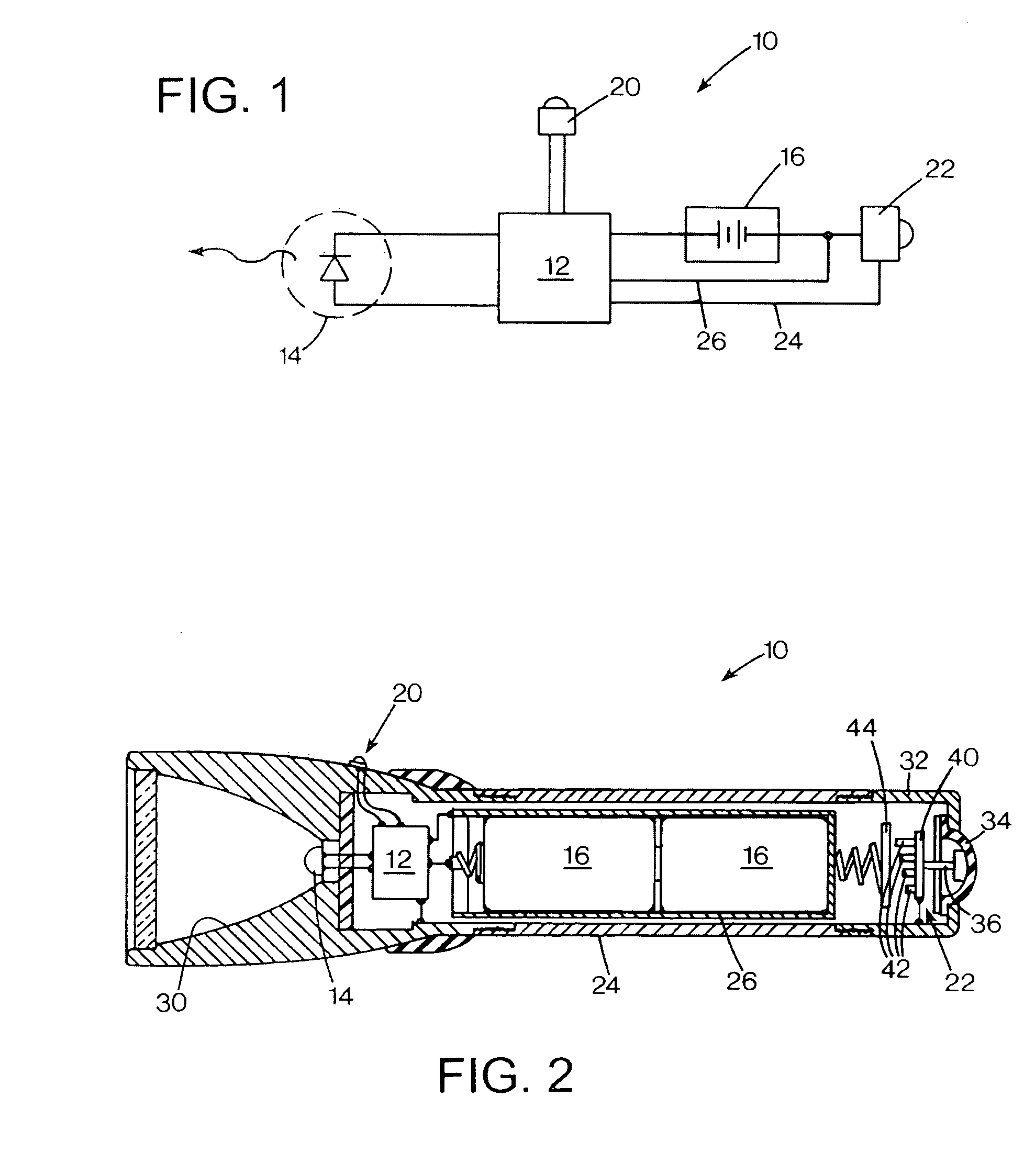
The present invention is a flashlight with a long body that has two ends. It has a powerful white light source at one end and several other lamps with different colors. The flashlight has a switch that can change which color is turned on by selecting different lamps. The flashlight also has a battery and control circuitry to manage the lamps. This invention solves the problem of limited options in previous flashlights.

Problems solved by technology

The technical problem addressed in this patent text is the limitations of existing flashlights in terms of the ability to emit light at different levels and colors, and the need for a more versatile and efficient light source for emergency and critical applications. Previous flashlights have required the user to maintain button pressure or rotate a switch to change the brightness or color of the light, which can be inconvenient and time-consuming. The patent text proposes a solution to these limitations by providing a flashlight with a programmable light source that can be controlled through a single switch to achieve different levels of light output and color options.

Method used


Image

  • Flashlight with adjustable color selector switch
  • Flashlight with adjustable color selector switch
  • Flashlight with adjustable color selector switch

Examples


embodiment

Variable Color Embodiment

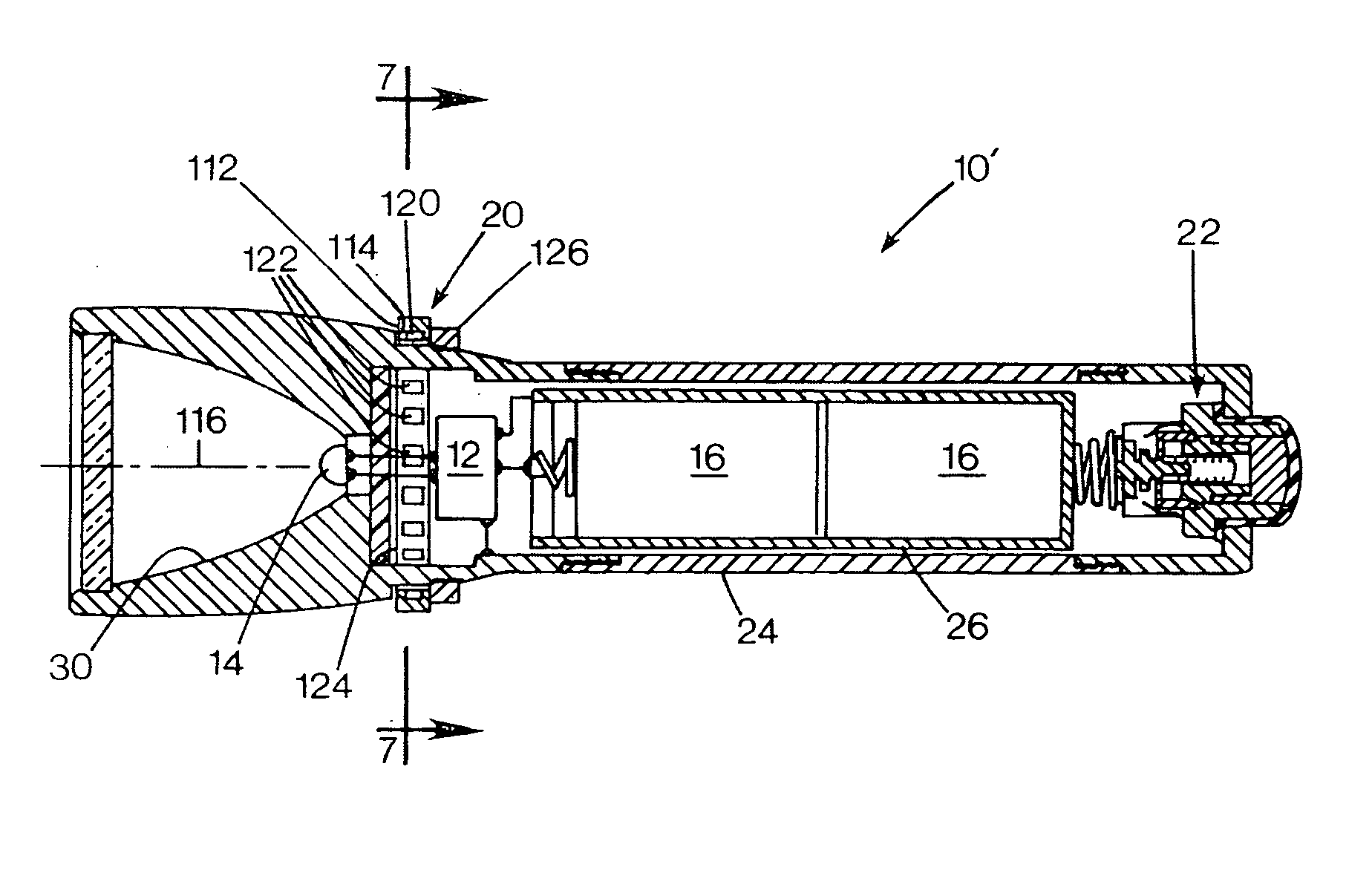
[0074]FIG. 14 shows a flashlight FIG. 6 shows a flashlight 510 that is essentially the same in many respects as that shown in FIG. 6, with an output control 520 in the form of an annular ring 522 that encircles the periphery of the flashlight's housing 524 at the forward portion that houses a lamp assembly 514. The ring is oriented in a plane perpendicular to the flashlight housing and optical axis 516, and are concentric with the cylindrical housing portion. As illustrated schematically in FIG. 6, the ring includes an embedded magnet facing toward the center of the ring, and the flashlight includes a plurality of Hall effect magnetic field sensors that operate to detect whether or not the magnet is adjacently positioned. The sensors are connected to the control circuit 512, which receives a signal to determine the angular position of the ring at any time. The sensors may be configured as discussed and illustrated above with respect to FIGS. 6 and 7. With th...


PUM


Abstract

A flashlight having an elongated body having opposed first and second ends. A first lamp is a high-intensity variable brightness white light source located at the first end. A number of additional lamps are positioned at the first end. The additional lamps include at least two different output wavelengths different from each other and from the first lamp. A first switch on the flashlight selectively operates to select the output wavelength of the flashlight by selectively enabling different lamps based on the condition of the switch. A power storage element and control circuitry are connected to the lamps and to the switch.

Description


Claims


Application Information

Patent Timeline
Owner SUREFIRE LLC
Why Eureka
Try Eureka