Printer equipped with cutter mechanism

a cutter and printing machine technology, applied in printing, metal working equipment, other printing equipment, etc., can solve the problems of limited space around the cutter, possible exposure of the cutter to the outside, and impairment of the cutter

Inactive Publication Date: 2005-06-09
SEIKO EPSON CORP
View PDF16 Cites 43 Cited by
  • Summary
  • Abstract
  • Description
  • Claims
  • Application Information

AI Technical Summary

Benefits of technology

[0007] It is therefore an object of the invention to provide a mechanism that is able to achieve a state in which the cutter will not be exposed

Problems solved by technology

However, when the door cover is opened, the cutter may possibly be exposed to the outside, and the cutter may be impaired.
With a printer of a medium or large size in which spaces are allowed around the cutter, the above c

Method used


Image

  • Printer equipped with cutter mechanism
  • Printer equipped with cutter mechanism
  • Printer equipped with cutter mechanism

Examples


first embodiment

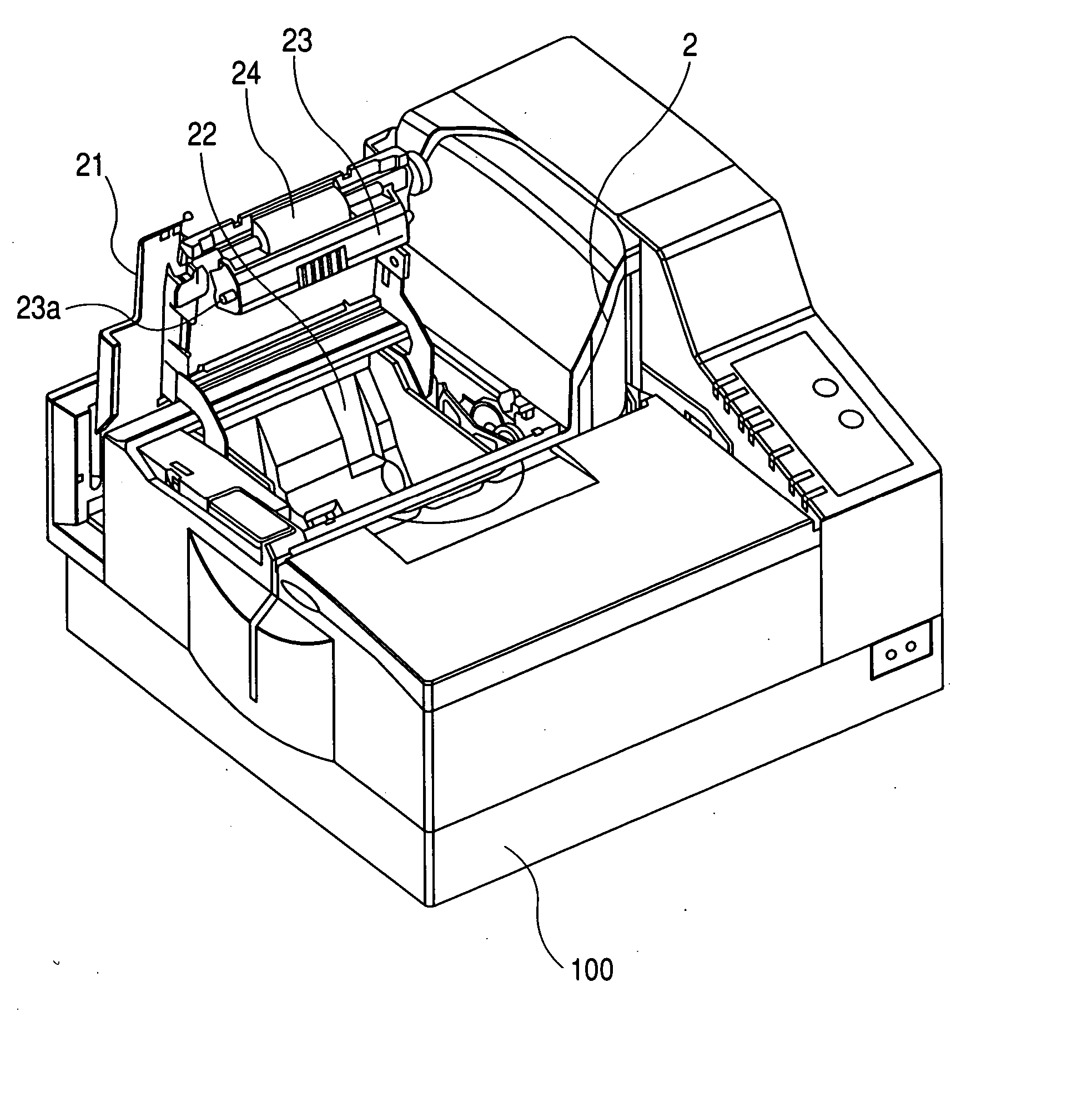
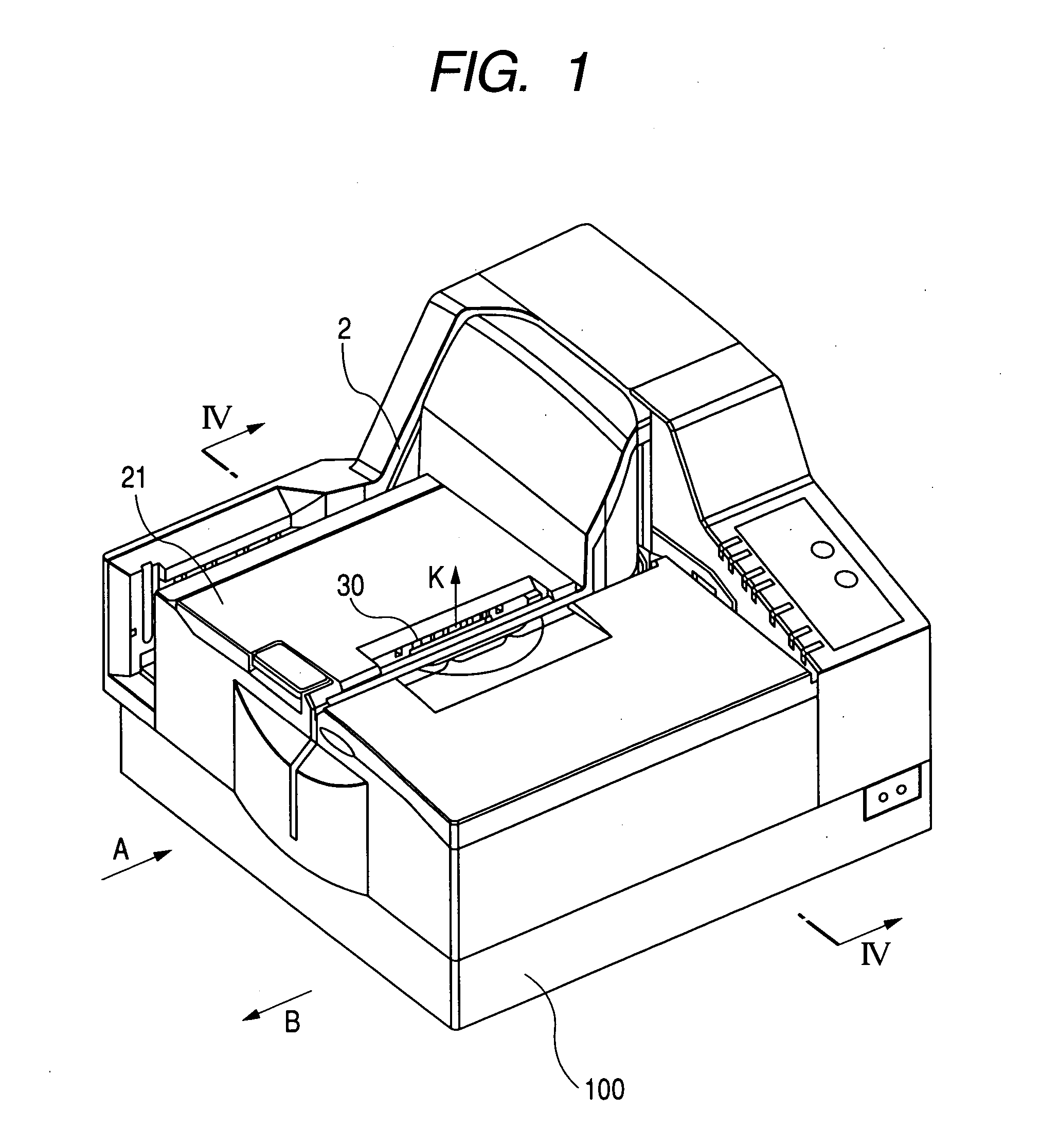
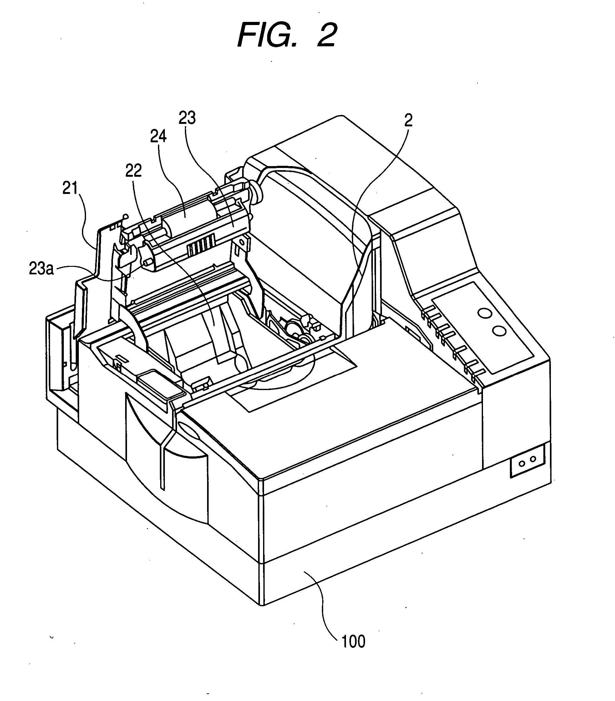
[0063] As shown in FIGS. 1 to 4, a printer 100 according to the invention is provided with a first print mechanism 1 to read or print an image while transporting a cut sheet 3 through a U-shaped transportation path, and a second print mechanism 5, having a transportation path orthogonally intersecting with the U-shaped transportation path, to perform printing on a rolled recording sheet 20.

[0064] In the first print mechanism 1, a cut sheet 3 is inserted into the U-shaped transportation path 2 in a direction indicated by arrow A, an image or information pre-printed in magnetic ink on the cut sheet 3 is read by a scanner or an MICR (Magnetic Ink Character Reader) while the cut sheet 3 is being transported through the transportation path 2; printing is performed on the cut sheet 3 by a print head 14; and the cut sheet 3 is ejected in a direction indicated by arrow B. In the second print mechanism 5, printing is performed by the same print head 14 while transporting a recording sheet 20...

second embodiment

[0112] According to the cutter mechanism in the second embodiment as described above, the side face angle of the cutting edge of the cutter 32 is set to maximize sharpness when the cutter 32 is at the cutting position while the door cover 21 remains closed. While the door cover 21 is open, the side face of the cutting edge of the cutter 32 abuts the inner wall 33a of the cutter cover 33, which causes the cutter 32 and the cutter cover 33 to be placed integrally, thereby saving space in the printer 100.

[0113] Next, a printer according to a third embodiment of the invention will be described below with reference to FIGS. 12 and 13. Elements similar to those in the second embodiment will be designated by the same reference numerals and repetitive explanations for those will be omitted. This embodiment is characterized by the combination of the cutter storing mechanism in the first embodiment and the cutter shape in the second embodiment.

[0114] Specifically, a cutter 34 is bent at an o...


PUM


Abstract

A rolled sheet is accommodated in an accommodating section. A cover is movable between an open position for opening the accommodating section and a closed position for covering the accommodating section. A part of the rolled sheet fed from the accommodating section is transported through the transporting path. A print head is disposed in a first side relative to the transporting path and operable to perform printing on the part of the rolled sheet in the transporting path. A cutter is disposed in the first side and movable between an operable position at which the cutter is operable to cut the part of the rolled sheet and a covered position at which the cutter is not operable to cut the part of the rolled sheet. The cutter is moved to the operable position when the cover is moved from the open position to the closed position, and is moved to the covered position when the cover is moved from the closed position to the open position. A cutter cover covers the cutter in the covered position.

Description

BACKGROUND OF THE INVENTION [0001] The present invention relates to a printer capable of performing printing with respect to a rolled recording sheet and equipped with a cutter mechanism for cutting the rolled recording sheet. [0002] A printer capable of accommodating a rolled recording sheet therein has been known, performing printing on the recording sheet with a print head while feeding the recording sheet with a feeding roller. When printing is finished, the recording sheet led out from a sheet outlet of the printer is cut with a cutter disposed at the sheet outlet. [0003] The cutter may be a manual cutter configured such that a recording sheet is pressed against a stationary blade disposed at the sheet outlet. Alternatively, the cutter may be an automatic cutter that cuts the recording sheet by actuating a movable blade with a driving force from a motor or the like. [0004] When the rolled recording sheet is replaced, a housing section needs to be released by opening a door cove...

Claims


Application Information

Patent Timeline
IPC IPC(8): B41J11/66B26D7/22B41J11/70
CPCB41J11/70B26D7/22Y10T83/8749B41J11/04B41J11/66
Inventor OSHIDA, KAZUYAKOMAKI, TAKESHI
Owner SEIKO EPSON CORP
Why Eureka
Try Eureka