TV & FM transmitting system early warning monitoring

a transmission system and early warning technology, applied in the direction of transmission monitoring, transmitter monitoring, modulation, etc., can solve problems such as unbalanced feed transmission

Inactive Publication Date: 2005-06-09
BENDOV ODED
View PDF8 Cites 12 Cited by
  • Summary
  • Abstract
  • Description
  • Claims
  • Application Information

AI Technical Summary

Problems solved by technology

An unbalanced feed transmission-line is coupled to the input port of the antenna, for coupling power originating from the source to the antenna for generating electromagnetic radiation therefrom.

Method used


Image

  • TV & FM transmitting system early warning monitoring
  • TV & FM transmitting system early warning monitoring
  • TV & FM transmitting system early warning monitoring

Examples


Embodiment Construction

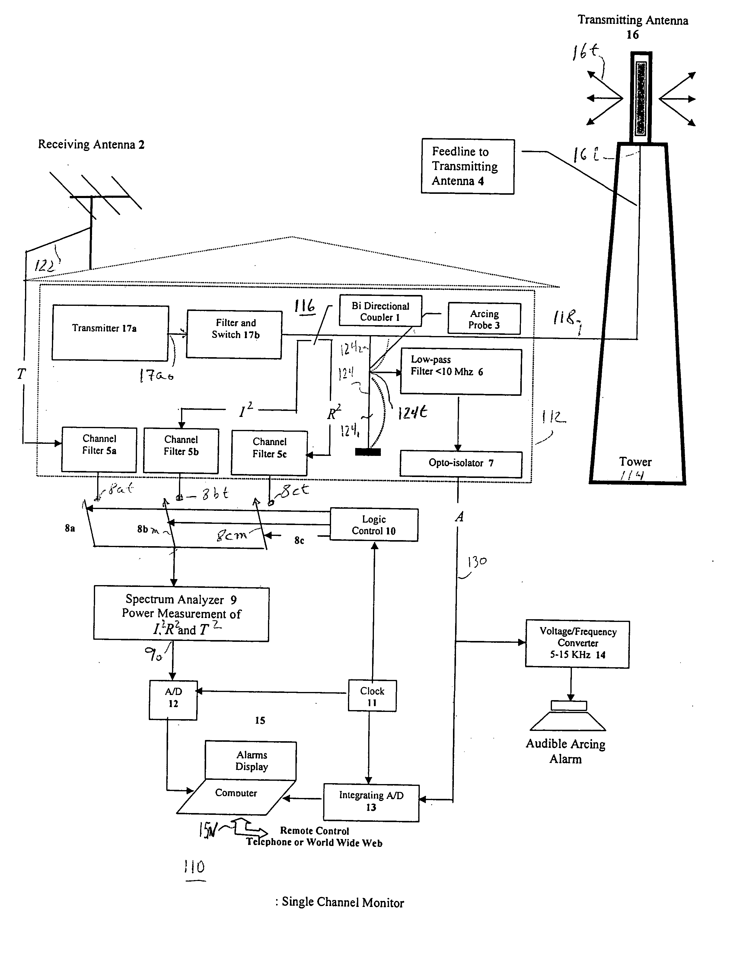
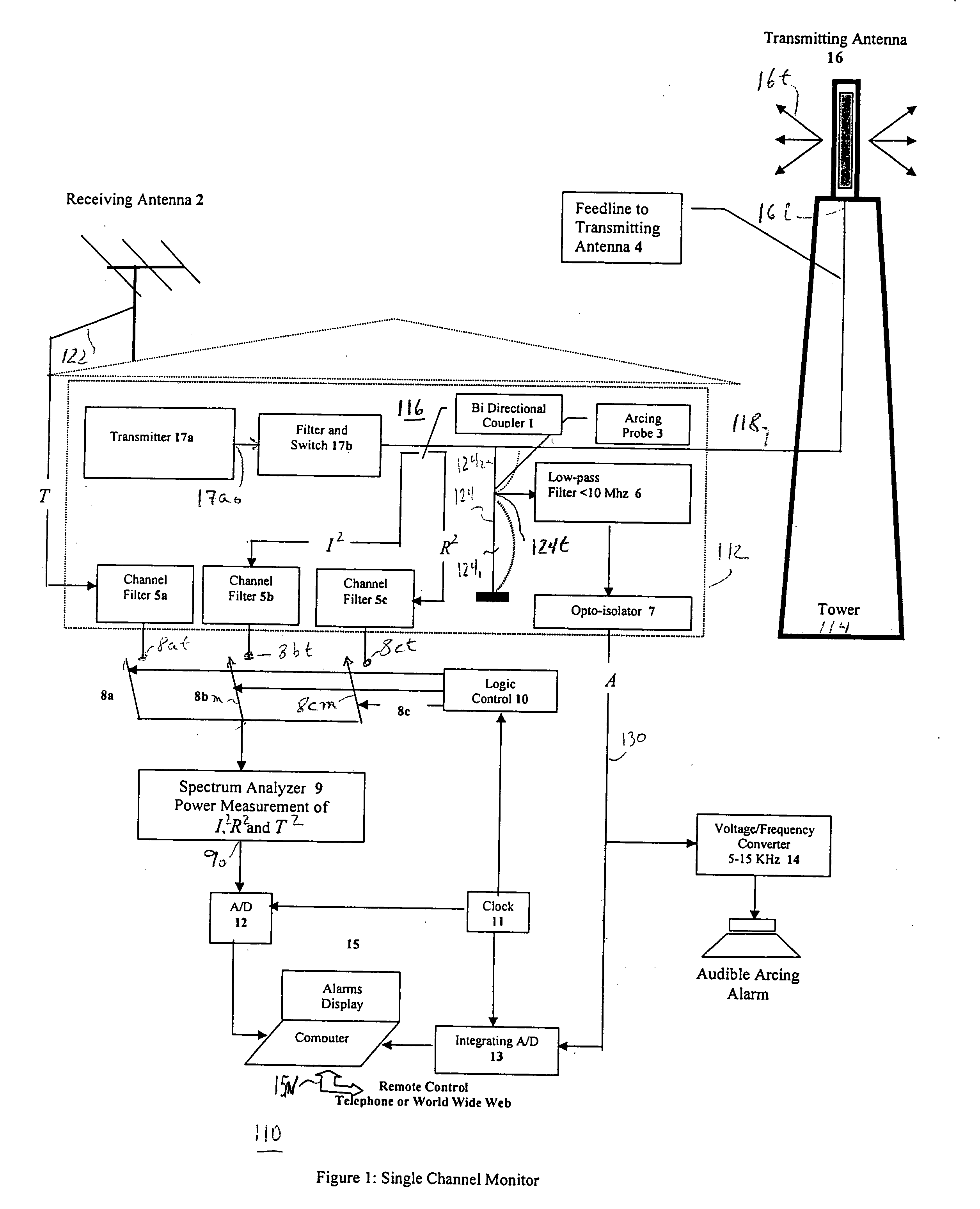
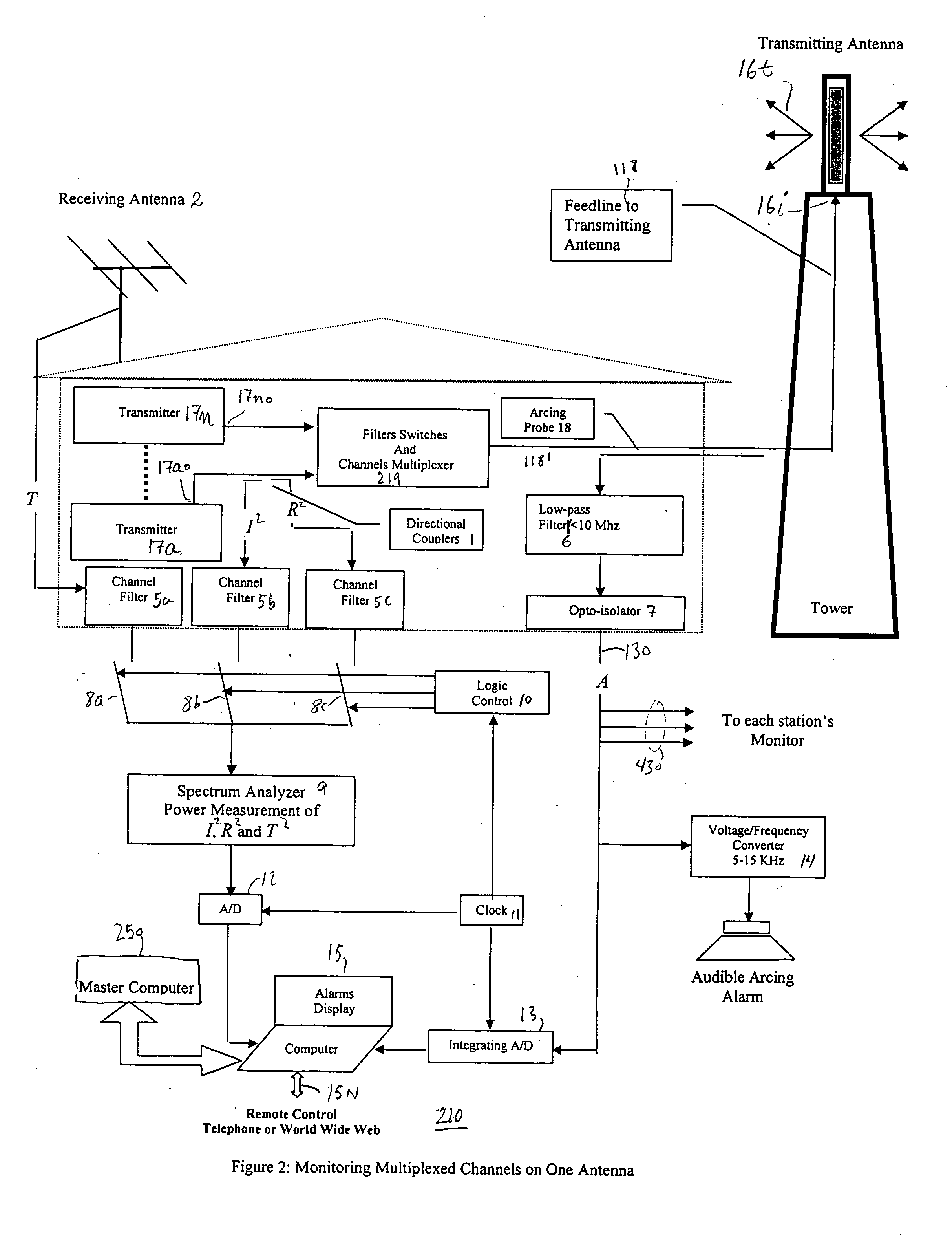
[0023] Prior to the present invention there have been no systems and methods that would provide reliable early warning of arcing or overheating in TV and FM broadcast antennas and in their feedlines. Prior to the present invention, failure reporting methods have been based solely on measuring the power (or voltage) being reflected back toward the transmitter, sometimes together with measurement of the loss of gas pressure inside the feedlines. Those methods provided protection for the transmitter from reflected power, but did not prevent the transmitter from continuing to supply power to the overheating or arcing areas inside the feedlines until after the burnout was almost complete. That occurred because, while power would be supplied to the failing areas, only a small portion of it, if any at all, would be reflected back, and might not be sensed. Consequently, the damage might continue to increase until a catastrophic failure materialized. Only at times near or after catastrophic ...


PUM


Abstract

A computerized monitoring apparatus processes signals representing (a) incident power I2 to an antenna, (b) reflected power R2, radiated power T2, and arc voltage power A2. The monitor provides warning of arcing or overheating in the feedlines to (and inside) the antenna before catastrophic failure. Early warning of developing failures allows for orderly transition to standby transmission and avoids losing on-air time. The monitoring apparatus also provides a failsafe indication of whether power is delivered to the antenna and whether the antenna radiates the power delivered to it. Such failsafe indication is required before personnel are allowed near the antenna. The apparatus measures the relative power density at specified locations near and on the tower, and compares the measured RFR exposure density to that allowable by the Federal Communications Commission. The monitoring apparatus can be applied to multiple transmitters with multiple channel combiners feeding a common antenna connection.

Description

CROSS REFERENCE TO RELATED APPLICATIONS [0001] This application relates to and claims the benefit of the earlier filing date under 35 U.S.C. 119, of U.S. Provisional Patent Application Ser. No. 60 / 528,050 entitled “EARLY WARNING MONITORING METHOD, SYSTEM AND APPARATUS FOR TELEVISION AND FM RADIO TRANSMITTING ANTENNAS AND COAXIAL FEEDLINES,” filed on Dec. 9, 2003.FIELD OF THE INVENTION [0002] This invention relates to the monitoring of electromagnetic transmitting arrangements for fault identification and / or safety. BACKGROUND OF THE INVENTION [0003] Television and FM electromagnetic signals are radiated from transmitting systems which ordinarily include an electrical signal generator or transmitter, which produces signals modulated by the desired audio and / or video program, and possibly by data in some situations. The transmitter produces signals which become available as guided waves at a transmission-line port of the transmitter. In order to generate radiated or unguided electroma...

Claims


Application Information

Patent Timeline
Patent Type & Authority Applications(United States)
IPC IPC(8): H01Q1/00H04B17/00
CPCH01Q1/002H04B17/17H04B17/103
Inventor BENDOV, ODED
Owner BENDOV ODED
Why Eureka
Try Eureka