Orthopedic implant with angled pegs

a technology of orthopedic implants and pegs, which is applied in the field of orthopedic implants, can solve the problems of requiring a significant amount of space above the prepared joint surface for up and down movement, and achieve the effect of facilitating implantation

Active Publication Date: 2005-06-09
HOWMEDICA OSTEONICS CORP
View PDF5 Cites 91 Cited by
  • Summary
  • Abstract
  • Description
  • Claims
  • Application Information

AI Technical Summary

Benefits of technology

[0007] It is one object of the invention to provide an orthopedic implant having a bottom surface with bone engaging features such as stems or pegs angled with respect to the bone contacting surface so that implantation is facilitated.
[0012] Preferably, the angle between the bone contacting surface and the peg axis is between 30° and 85° and more preferably between 30° and 45°. Preferably, the angle of the peg axis with respect to the anterior-posterior plane is between 15° and 60° and the even more preferably between 30° and 45°. In the tibial implant, these pegs are angled so that one of the at least two pegs extends into an area of the resected medial condyle and the other peg extends into the area of the resected lateral condyle. The condyles of the tibia are of course prepared by boring holes at the desired angles to receive the pegs on the prosthetic tibial baseplate. To facilitate orienting the pegs on the baseplate with the pre-drilled bores and the prepared proximal tibia, the pegs may be made modular and / or orientable at a desired angle to match the pre-drilled holes. In a modular embodiment, the end of the peg which contacts the bottom or bone contacting surface of the tibial baseplate is conically tapered to match a conically tapered bore in the baseplate itself. The tapers are preferably locking tapers so that the tapered surfaces lock the peg in the desired angular orientation.

Problems solved by technology

The problem with stems or pegs which extend generally perpendicular to the bone contacting surface of the implant is that they require a large space so that the implant may be moved into position above holes prepared in the bone surface and then moved towards the bone so that the pegs and stem on the prosthesis can engage the corresponding holes in the prepared bone in a co-axial manner.
Obviously, this up and down movement requires a significant amount of room above the prepared joint surface.

Method used


Image

  • Orthopedic implant with angled pegs
  • Orthopedic implant with angled pegs
  • Orthopedic implant with angled pegs

Examples


Embodiment Construction

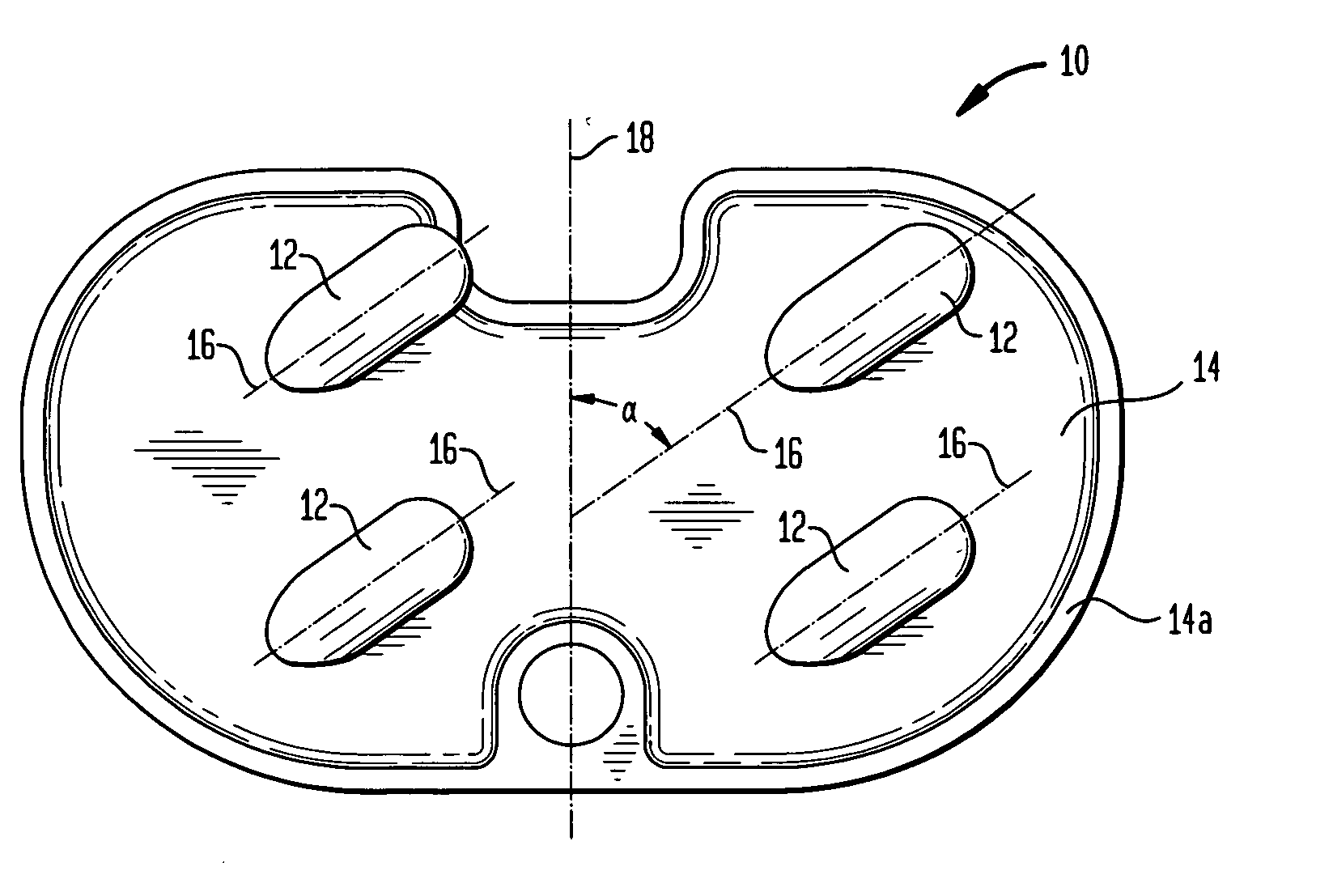
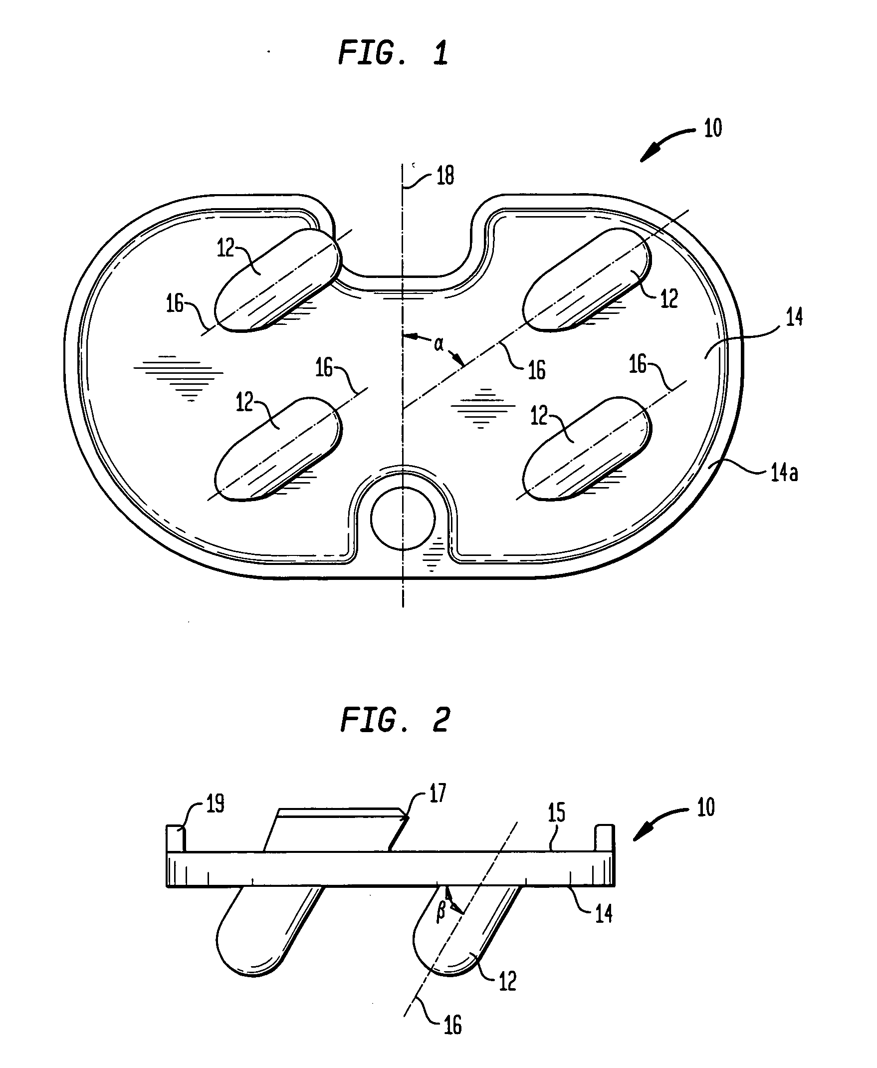
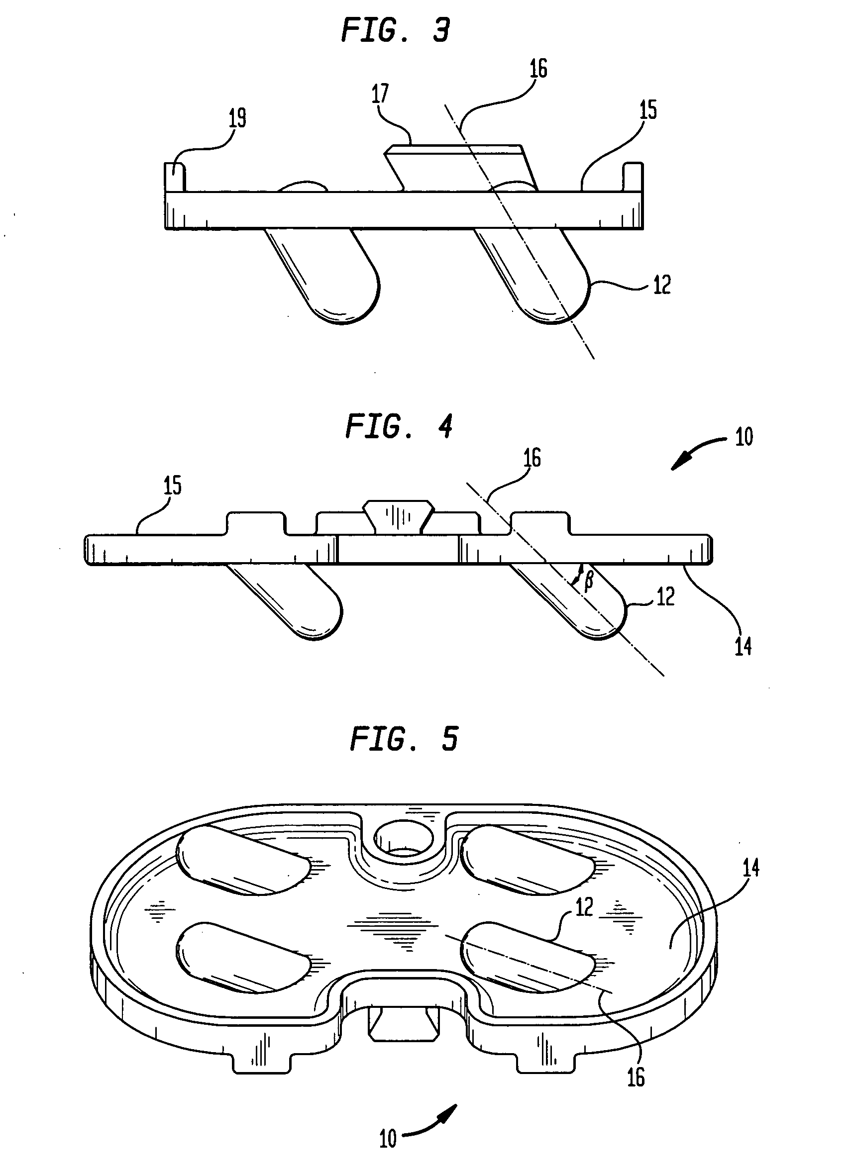
[0025] Referring to FIGS. 1 and 5, there is shown a bottom view of a typical tibial baseplate 10 which, in the preferred embodiment, includes four pegs 12 mounted on a bottom bone contacting surface 14 of baseplate 10. Surface 14 may be surrounded by a rim 14a. Each peg 12 includes a longitudinal axis 16 which is angled with respect to an anterior-posterior plane 18 through baseplate 14. Pegs 12 are thus also at an angle with respect to the surface 14. Although four pegs are shown, only one, two or three pegs could be used.

[0026] As can be seen in FIG. 1, longitudinal axis 16 of pegs 12 is oriented with respect to α anterior-posterior plane 18 by an angle α. For convenience, α is measured as the acute angle the pegs make with plane 18. In the preferred embodiment, α varies between 5° to 90° with respect to the anterior-posterior plane. Note that at 90° the pegs extend either purely medially or purely laterally. At 5° the longitudinal axis 16 of the pegs is oriented 5° from plane 18...


PUM

PropertyMeasurementUnit
angleaaaaaaaaaa
angleaaaaaaaaaa
angleaaaaaaaaaa

Abstract

An orthopedic implant, such as a tibial tray, includes a body having a bone contacting surface with at least one and preferably two pegs extending from the bone contacting surface. Each of the pegs has a longitudinal axis angled with respect to the bone contacting surface and also angled in at least one direction consisting of a medial-lateral direction, an anterior-posterior direction and an inferior-superior direction. In the case of the tibial tray, the pegs form a non-perpendicular angle with the bone contacting surface of the baseplate and are angled in both a posterior direction and a medial or lateral direction.

Description

BACKGROUND OF THE INVENTION [0001] This invention relates to an orthopedic implant having a bone contacting surface with pegs angled to facilitate implantation of the implant into a prepared bone surface. More particularly, it relates to a tibial implant which has pegs angled in a medial or lateral direction and also in a posterior direction. [0002] Various orthopedic implants have used angled pegs to help stabilize the component after implantation. Various knee prosthesis, either tibial components or femoral components have short pegs extending perpendicularly to the bone contact surface in the condylar area to provide stability on implantation. Some of these implants include central stems which extend into the prepared marrow canal of a long bone. Short peg-like extensions are then provided in the condylar area to prevent rotation of the implant after implantation. For example, many tibial and femoral components are supplied with long central stems for engaging the medullary canal...

Claims


Application Information

Patent Timeline
Patent Type & Authority Applications(United States)
IPC IPC(8): A61F2/00A61F2/30A61F2/38A61F2/40
CPCA61F2/30767A61F2310/00796A61F2/4081A61F2002/30224A61F2002/30334A61F2002/30604A61F2002/30616A61F2002/30708A61F2002/30772A61F2002/30777A61F2002/30785A61F2002/30883A61F2002/30892A61F2220/0033A61F2230/0069A61F2250/0084A61F2/389
Inventor HOZACK, WILLIAM JAMESPLASKON, GREGORY E.
Owner HOWMEDICA OSTEONICS CORP
Why Eureka
Try Eureka