Method of compensating anisotropy in a vibrating-bell inertial rotation sensor

Active Publication Date: 2005-06-16
SAFRAN ELECTRONICS & DEFENSE
View PDF5 Cites 5 Cited by
  • Summary
  • Abstract
  • Description
  • Claims
  • Application Information

AI Technical Summary

Benefits of technology

[0008] In a preferred implementation of the invention, the gain difference between the electrodes is measured by multiplexing by means of a single processor system for a group of electrodes. Thus, for

Problems solved by technology

In addition, in existing systems, each electrode is connected to a processing system and the various processing systems may also pr

Method used


Image

  • Method of compensating anisotropy in a vibrating-bell inertial rotation sensor
  • Method of compensating anisotropy in a vibrating-bell inertial rotation sensor

Examples


Example

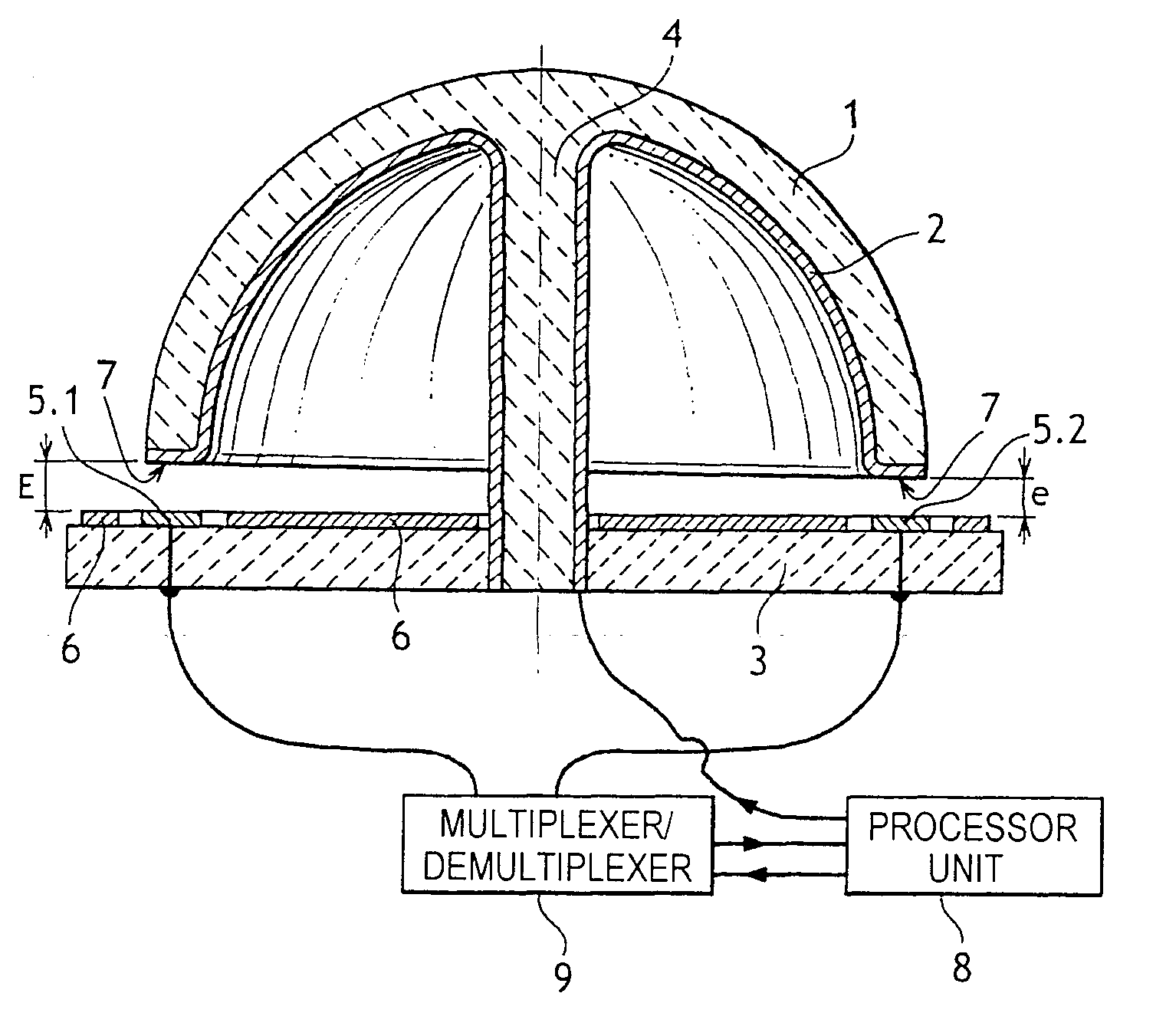
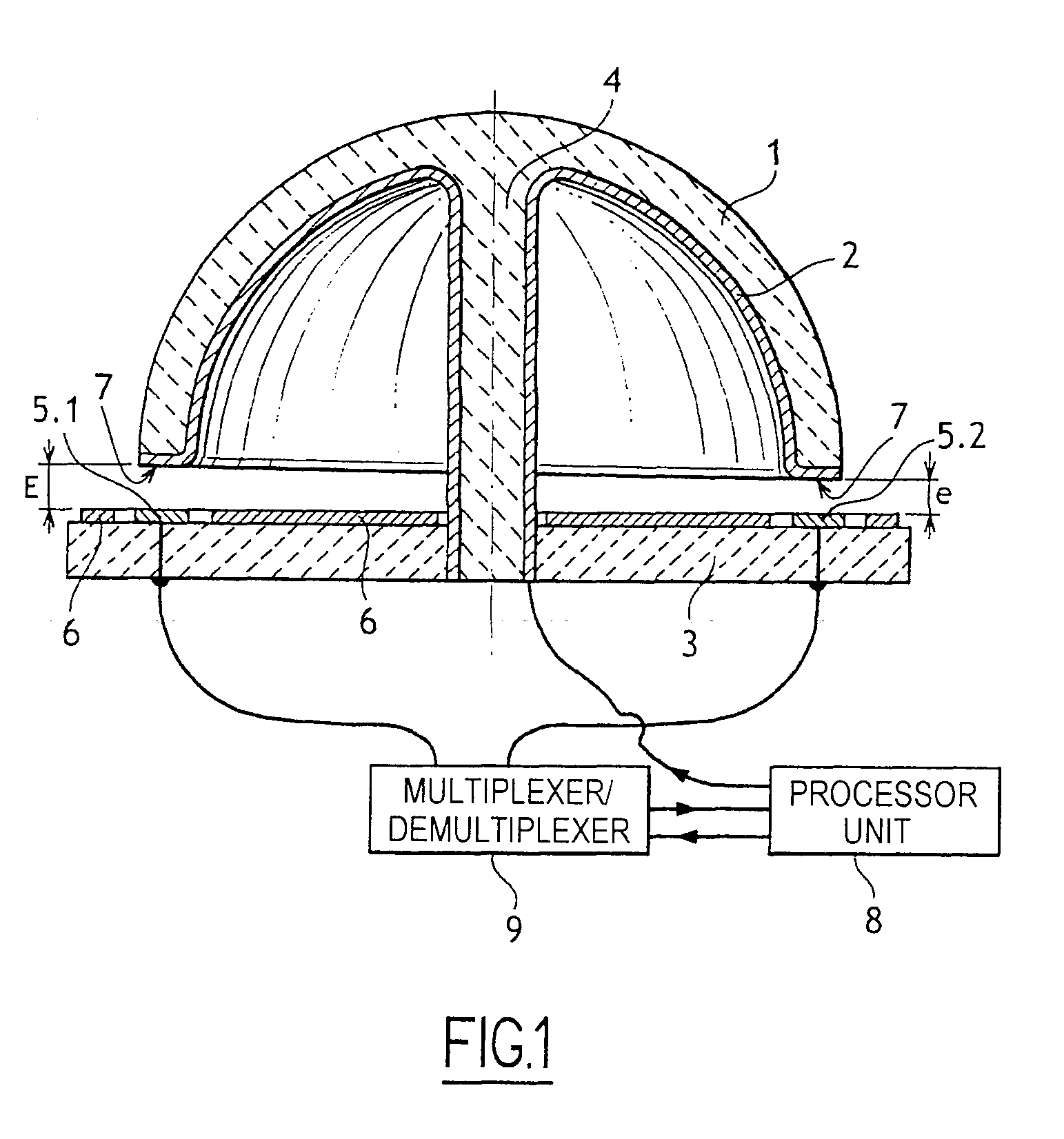
[0010] With reference to the figure, the compensation method of the invention is applied to an inertial rotation sensor comprising in conventional manner a vibrating bell 1, in this case a hemispherical bell made of silica and secured by a stalk 4 to a stand 3. The inside surface of the bell 1 and the end face of the edge of the bell and the stalk 4 are covered in a layer of metal 2 which is connected to a processor unit 8 in order to receive a direct current (DC) bias voltage. The stand 3 carries a guard electrode 6 and control and detection electrodes, generally eight in total, extending facing the edge 7 of the bell 1 and regularly distributed around the axis of the bell 1. The figure shows only two electrodes 5.1 and 5.2 that are diametrically opposite. These electrodes may equally well be control electrodes or detection electrodes. In the figure, the distance between the electrodes and the edge 7 of the bell has deliberately been exaggerated in order to show more clearly the di...


PUM


Abstract

The method serves to compensates anisotropy in an inertial rotation sensor comprising a metallized vibrating bell (1) having a bias voltage applied thereto, the vibrating bell (1) having an edge (7) electrodes (5.1, 5.2), and the method comprises the steps of measuring, preferably by multiplexing, the anisotropy between the electrodes and of applying to the electrodes a fraction of the bias voltage that depends on the differences measured between the electrodes.

Description

[0001] The present invention relates to a method of compensating anisotropy in a vibrating-bell inertial rotation sensor. BACKGROUND OF THE INVENTION [0002] Inertial rotation sensors are known that comprise a vibrating bell, generally a hemispherical bell, having its surface metallized to receive a bias voltage, the bell having an edge facing electrodes that are carried by a stand. The electrodes are subdivided into control electrodes and detection electrodes. Control signals are applied to the control electrodes so as to cause the vibrating bell to vibrate, thereby deforming the bell with deformations of orientation that is sensitive to rotation of the sensor. The detection electrodes serve to measure the orientation of bell deformations and, by suitable processing, to deduce therefrom the rotary movements of the sensor. The displacements of the resonator relative to the electrode-carrier stand at two ends of a diameter are equal in modulus and in sign when they result from control...

Claims


Application Information

Patent Timeline
IPC IPC(8): G01C19/5691G01C25/00
CPCG01C25/005G01C19/5691
Inventor CARON, JEAN-MICHELRAGOT, VINCENTRENAULT, ALAINJEANROY, ALAIN
Owner SAFRAN ELECTRONICS & DEFENSE
Why Eureka
Try Eureka