Die plate for a foil stamping machine

a foil stamping machine and die plate technology, applied in the field ofgraphic arts, can solve the problems of time-consuming and undesirable use of flammable solvents in the conventional mounting of die plates

Inactive Publication Date: 2005-06-16
TMS TECH
View PDF4 Cites 7 Cited by
  • Summary
  • Abstract
  • Description
  • Claims
  • Application Information

AI Technical Summary

Problems solved by technology

However, there is required within the process some compressibility to ensure a quality image is applied to the substrate.
Ac

Method used


Image

  • Die plate for a foil stamping machine
  • Die plate for a foil stamping machine
  • Die plate for a foil stamping machine

Examples


Embodiment Construction

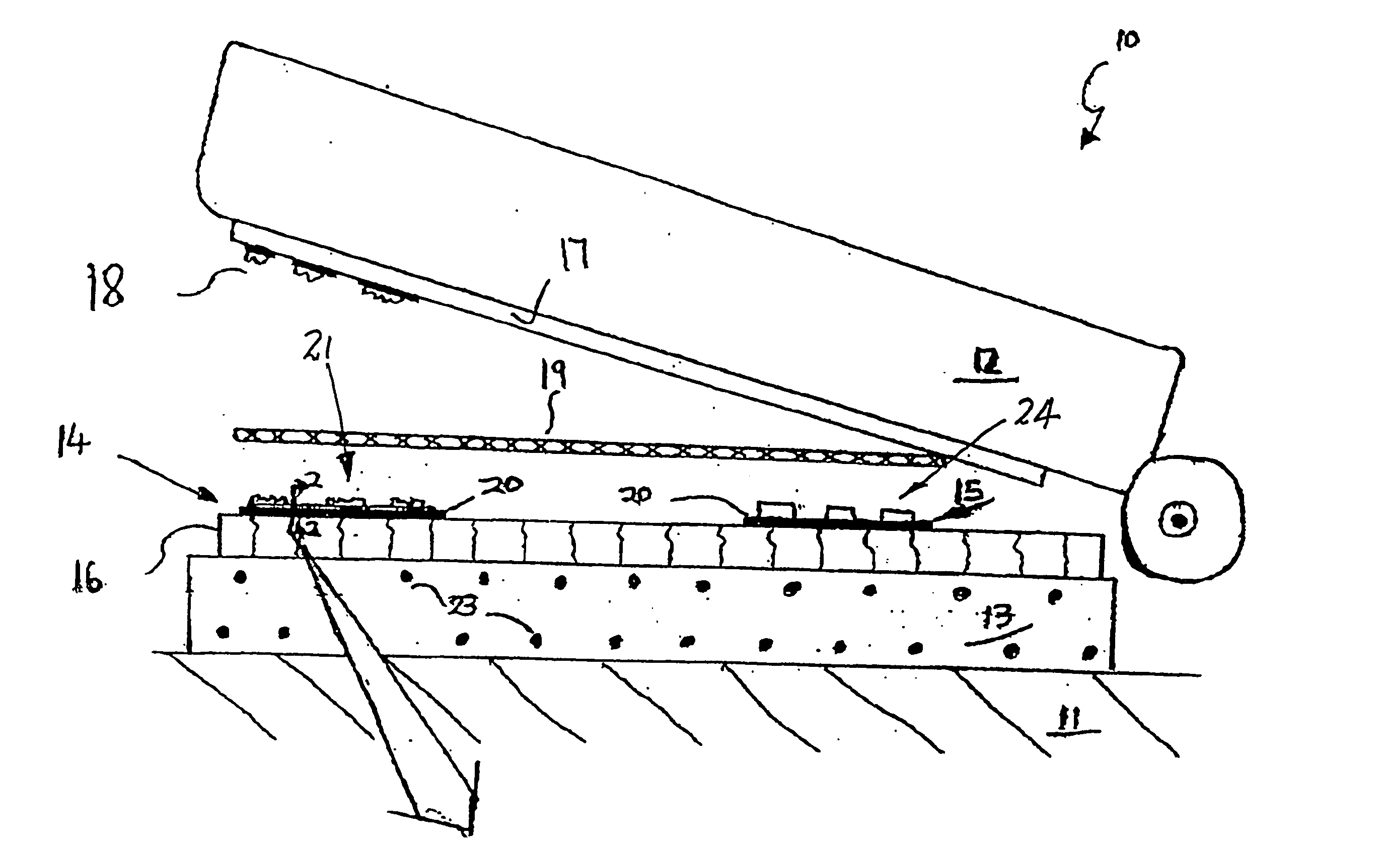
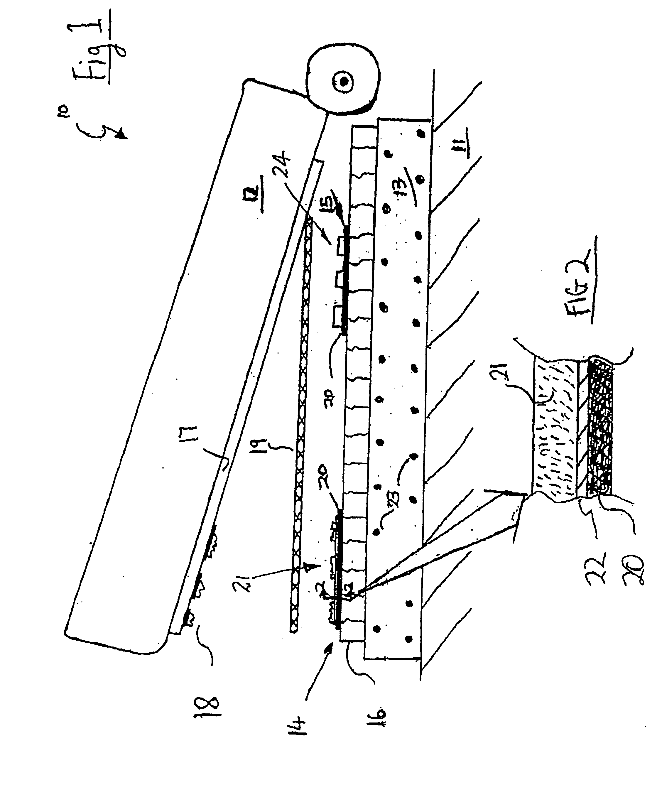
[0023] In FIGS. 1 and 2 of the accompanying drawings there is schematically depicted a foil stamping machine 10. The machine 10 includes a base 11 upon which there is pivotally mounted a platen 12. Secured to the base 11 is a bed 13 which is electrically heated by means of heating elements 23. Secured to the bed 13 is a magnetic holding device 16. Typically, the device 16 would be the magnetic holding device described in either of the above-mentioned patent publications.

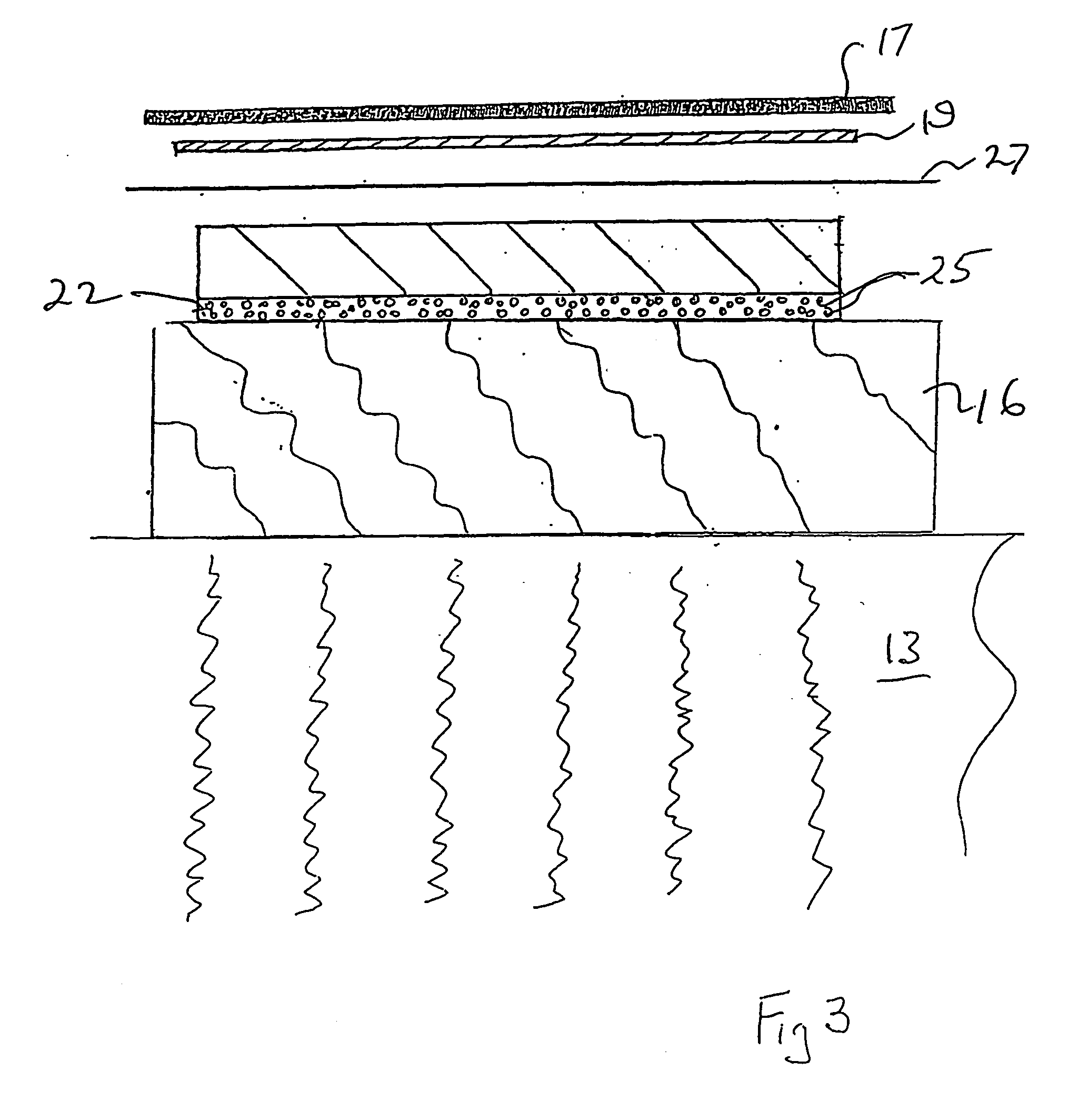
[0024] Secured to the device 16 by magnetic attraction are die plates 14 and 15. To cooperate with the die plates 14 and 15 is a jacket member (packing) 17, which is secured to the platen 12, having image portions 18. Preferably, the member 17 is a non-magnetic stainless steel or other non-magnetic metal. The image portions 18 are typically formed of fibreglass. If a foil image is to be applied to a substrate 19, a foil layer (27, FIGS. 3 and 4) is located between the substrate 19 and the die plate 14. The platen 12...


PUM

PropertyMeasurementUnit
Thicknessaaaaaaaaaa
Thicknessaaaaaaaaaa
Thicknessaaaaaaaaaa

Abstract

A die plate (14) to be used in a foil stamping machine (10). The die plate (14) includes a plate steel back (20) to which there is secured an image layer (21). The image layer (21) is secured to the plate steel back (20) by means of a compressible adhesive (22). Preferably, the adhesive (22) is an acrylic polymer. The image layer (21) is formed of metal such as brass, steel, copper, zinc, aluminium, magnesium, or photo-polymer.

Description

TECHNICAL FIELD [0001] The present invention relates to the field of graphic arts and more particularly to die plates employed in stamping machines such as foil stamping machines. BACKGROUND OF THE INVENTION [0002] Described in International Patent Publication No. WO 00 / 67953 and U.S. Pat. No. 5,904,096 are methods and apparatus relating to foil stamping. [0003] The above-discussed publications disclose a magnetic holding device to secure a steel-backed polymer die plate to a foil stamping heating element. [0004] Conventionally, the die plates are rigid, except for silicon rubber dies. Typically, the image layer is provided by magnesium, brass, copper, steel, zinc or a photo-polymer. However, there is required within the process some compressibility to ensure a quality image is applied to the substrate. Conventionally, the compression takes place in the packing, that is, the material behind the substrate. [0005] It is also the practice in foil stamping to correct low points in the d...

Claims


Application Information

Patent Timeline
IPC IPC(8): B41F27/02B21D33/00B41F16/00B41F27/00B41F27/04B44B5/00B44B5/02B44C1/14B44C1/24
CPCB44B5/026B44B5/0071
Inventor FAWCETT, ALAN J.WRIGHT, GLEN L.
Owner TMS TECH
Why Eureka
Try Eureka