
Emergency breathing tube

a technology for emergency breathing and fire victims, applied in breathing protection, breathing masks, life-saving devices, etc., can solve the problems of high mortality rate, inability of conventional fire escape systems to help in complex and constantly changing fire situations, and inhalation of poisonous gases, etc., to achieve the effect of reducing the mortality ra

Inactive Publication Date: 2005-06-16
HUANG SHANG LUNG
View PDF15 Cites 28 Cited by
  • Summary
  • Abstract
  • Description
  • Claims
  • Application Information

AI Technical Summary

Benefits of technology

[0005] Accordingly, an object of the present invention is to provide an emergency breathing tube that provides fresh air to people while they are waiting to be rescued from a fire, thereby reducing the mortality rate.
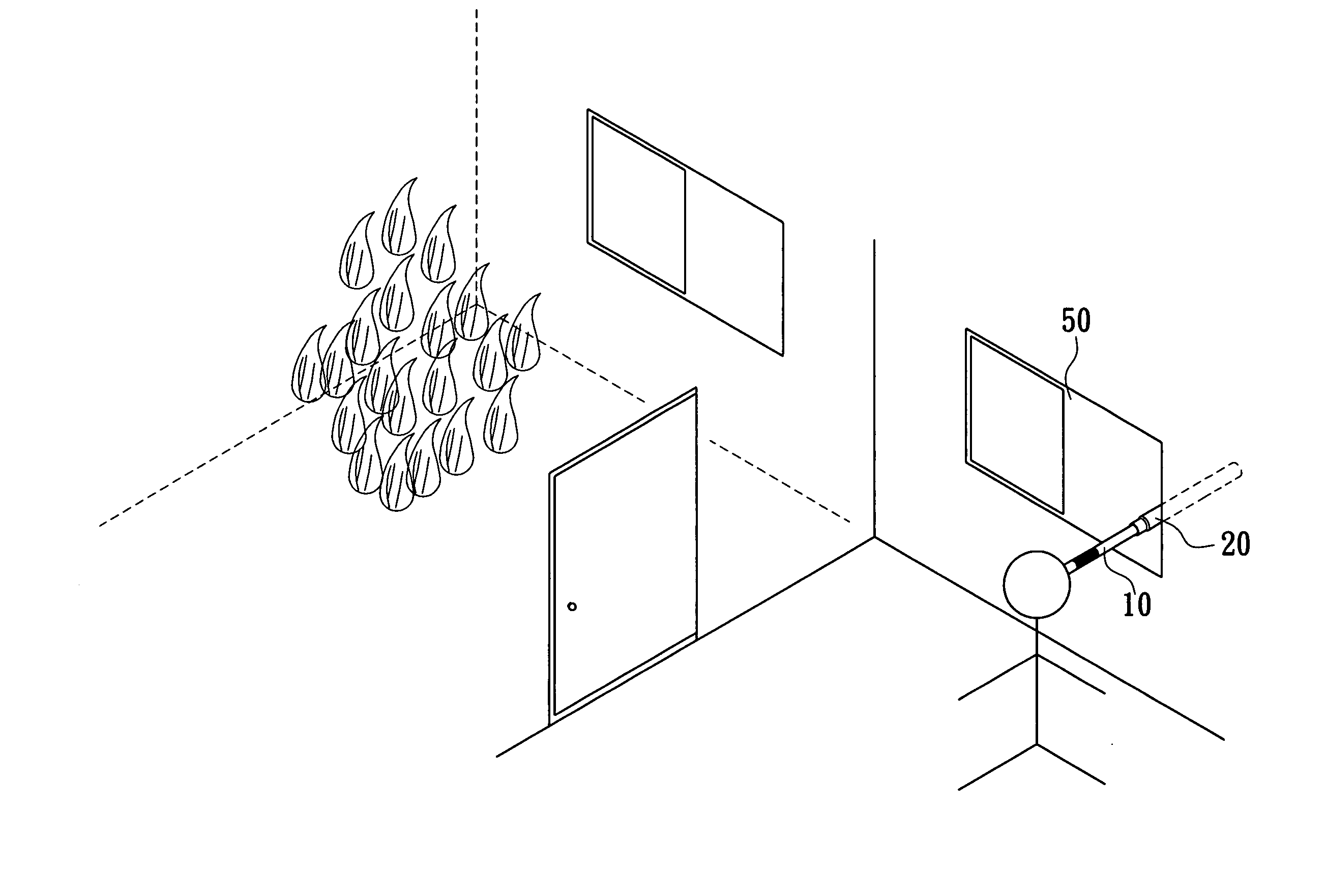
[0006] To attain the above object, the present invention provides an emergency breathing tube for fire victims, which breathing tube includes a first tube and a second tube. The first and second tubes couple together to form a retractile breathing tube with an adjustable length. When a fire occurs, a user can extend the breathing tube, hold one end of the breathing tube in the mouth, and then extend the other end thereof out from the smoky fire scene via an opening in the building to get fresh air. Thus, fir victims can survive a much longer time while waiting to be rescued, thereby reducing the mortality due to smoke inhalation.

Problems solved by technology

In practice, most fire victims die from inhaling highly poisonous gases, such as carbon monoxide, or a lack of oxygen.
Though conventional fire escape systems, for example, emergency elevators, escape ladders and the like may help people to get away from a fire scene and to escape from danger, these conventional fire escape systems often cannot help in a complex and constantly changing fire situation.
Consequently, people caught in a fire often die from inhaling highly poisonous gases, or a lack of oxygen.

Method used


Image

  • Emergency breathing tube
  • Emergency breathing tube
  • Emergency breathing tube

Examples


Embodiment Construction

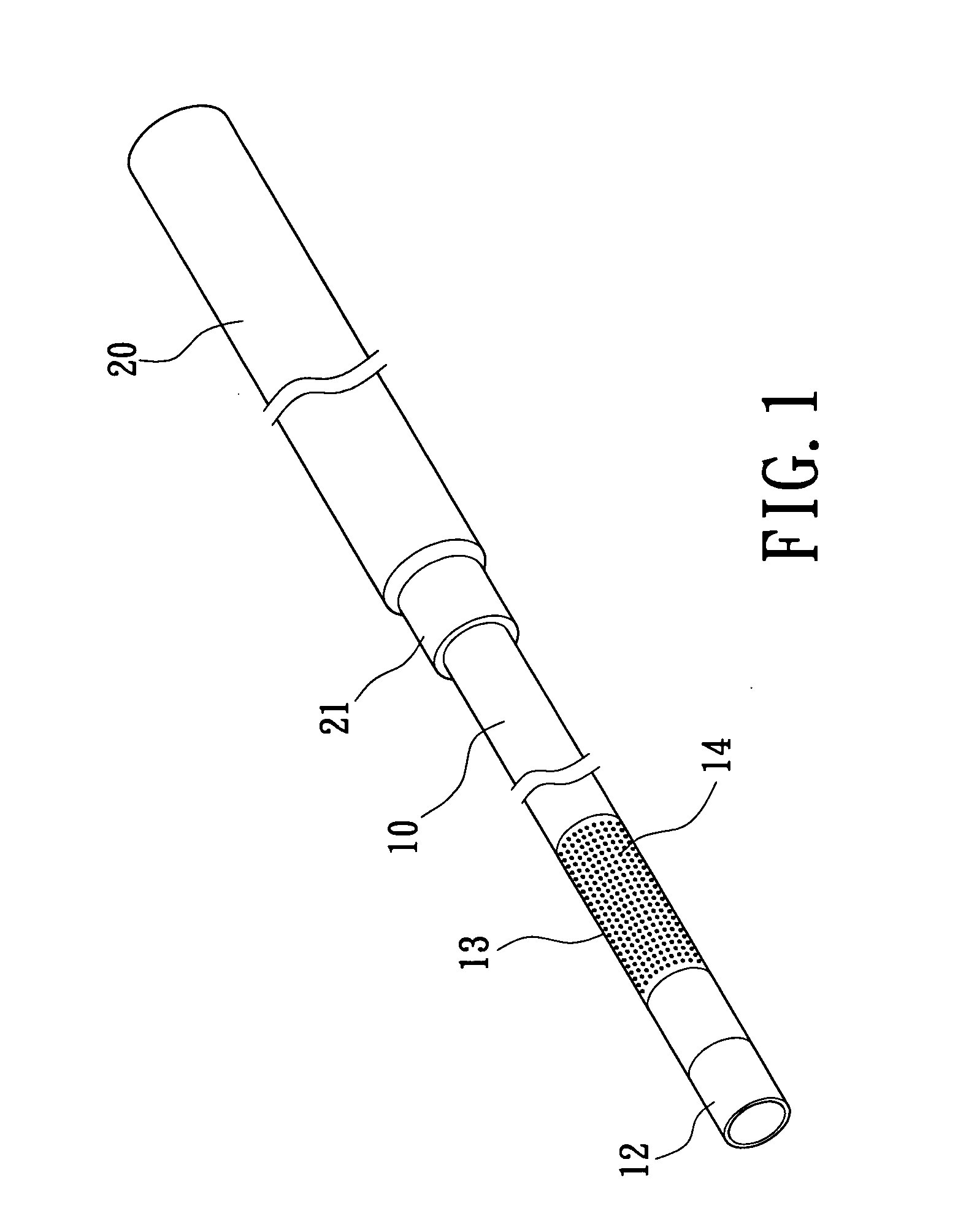
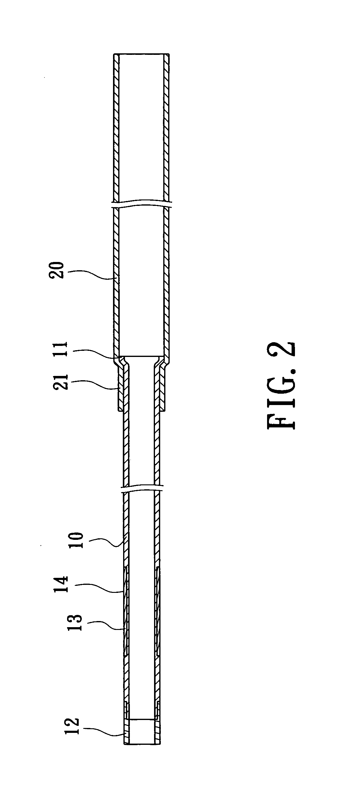
[0018] The present invention provides an emergency breathing tube for fire victims. FIG. 1 and FIG. 2 show the first embodiment of the present invention, which is a retractile breathing tube comprising a first tube 10 and a second tube 20. In order to withstand high temperatures in fire accident, the first tube 10 and the second tube 20 are made of a heat-resistant, easily molded material such as aluminum or the like, which is able to withstand a temperature of 300° C. The first tube 10 and the second tube 20 are hollow tubular bodies in a round shape or other suitable shapes and two opposite ends of each tube are open. An inner diameter of the second tube 20 is larger than an outer diameter of the first tube 10 so that the second tube 20 can contain the first tube 10. Then, the first tube 10 and the second tube 20 can couple together to form a retractile breathing tube, a length of which is adjustable. It is preferable that the breathing tube has a length of 2 meters or more when i...


PUM


Abstract

A tractable emergency breathing tube for life-saving in the event of fire includes a first tube and a second tube assembled together to form a series of telescoping tubes. The telescoping tubes are nested one within the other when the emergency breathing tube in a retracted stowed position. The inner tubes are latched in the stowed position by a caging mechanism. Furthermore, the emergency breathing tube can be extended until the final deployed position to reached out of the building on fire for fresh air. A user can inhale fresh air through the pursed mouth slowly by means of the instrument and exhale carbon dioxide through the nose rapidly, and repeat the above inhale / exhale procedures until being rescued.

Description

BACKGROUND OF THE INVENTION [0001] 1. Field of the Invention [0002] The present invention relates to an emergency breathing tube for fire victims, and more particularly to a breathing tube that people in a smoky fire scene can utilize to get fresh air from an outdoor location far away from the fire scene, thereby reducing injury and mortality due to inhaling highly poisonous gases, such as carbon monoxide, or due to lack of oxygen. [0003] 2. Description of Prior Art [0004] In practice, most fire victims die from inhaling highly poisonous gases, such as carbon monoxide, or a lack of oxygen. Though conventional fire escape systems, for example, emergency elevators, escape ladders and the like may help people to get away from a fire scene and to escape from danger, these conventional fire escape systems often cannot help in a complex and constantly changing fire situation. Consequently, people caught in a fire often die from inhaling highly poisonous gases, or a lack of oxygen. SUMMARY...

Claims


Application Information

Patent Timeline
Patent Type & Authority Applications(United States)
IPC IPC(8): A61M16/00A62B33/00A62B99/00
CPCA62B33/00
Inventor HUANG, SHANG LUNG
Owner HUANG SHANG LUNG
Learn More