Nested attachment junction for heat exchanger

a heat exchanger and nested technology, applied in the field of heat exchangers, can solve the problems of reducing the operating efficiency of the heat exchanger, and reducing the so as to maximize the efficiency and service life of the heat exchanger, and minimize or eliminate the possibility of leakage

Inactive Publication Date: 2005-06-16
HONEYWELL INT INC
View PDF26 Cites 6 Cited by
  • Summary
  • Abstract
  • Description
  • Claims
  • Application Information

AI Technical Summary

Benefits of technology

[0011] Heat exchangers of this invention, comprising the nested attachment junction, provide a connection between the header plate and shell that is both structurally secure and that operates to minimize or eliminate the possibility of leakage from the heat exchanger, thereby operating to maximize heat exchanger efficiency and service life.

Problems solved by technology

Conventional shell and tube heat exchangers used in such applications are known to be susceptible to leakage due to the nature and geometry of the attachment made between the header plate and the shell.
Such leakage is not desired as it can both reduce the operating efficiency of the heat exchanger and ultimately reduce the service life of the heat exchanger.

Method used


Image

  • Nested attachment junction for heat exchanger
  • Nested attachment junction for heat exchanger
  • Nested attachment junction for heat exchanger

Examples


Embodiment Construction

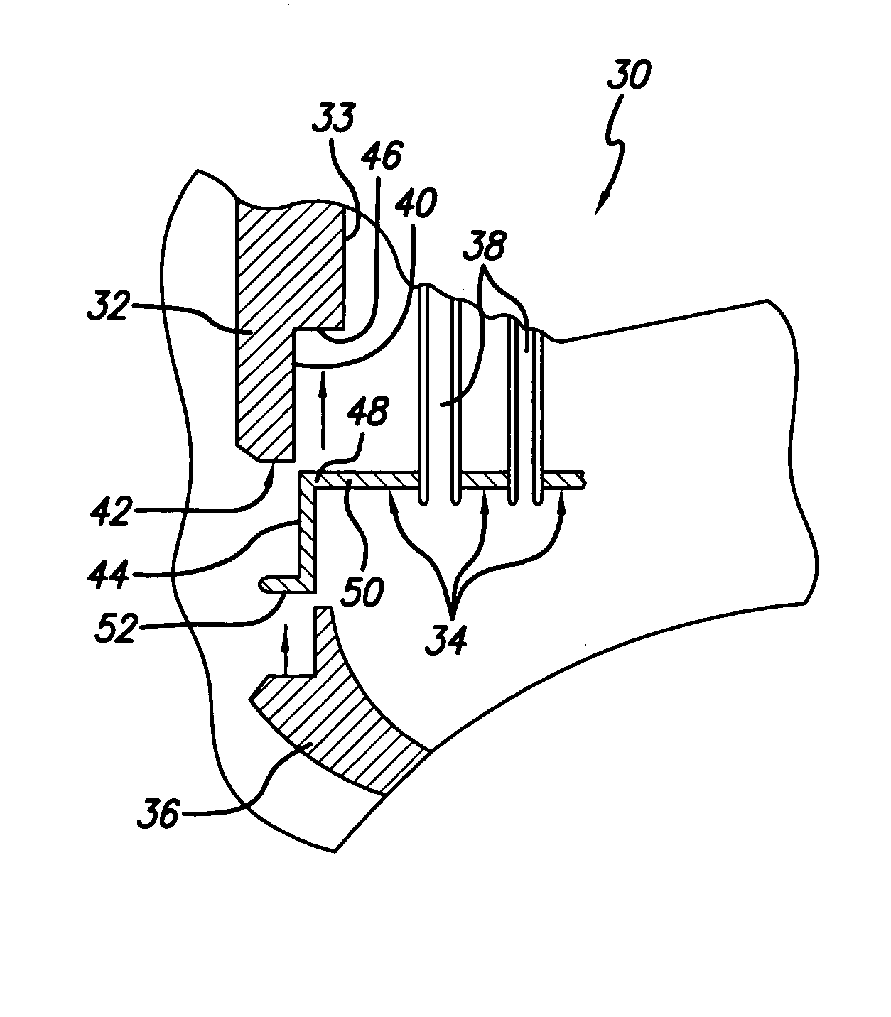
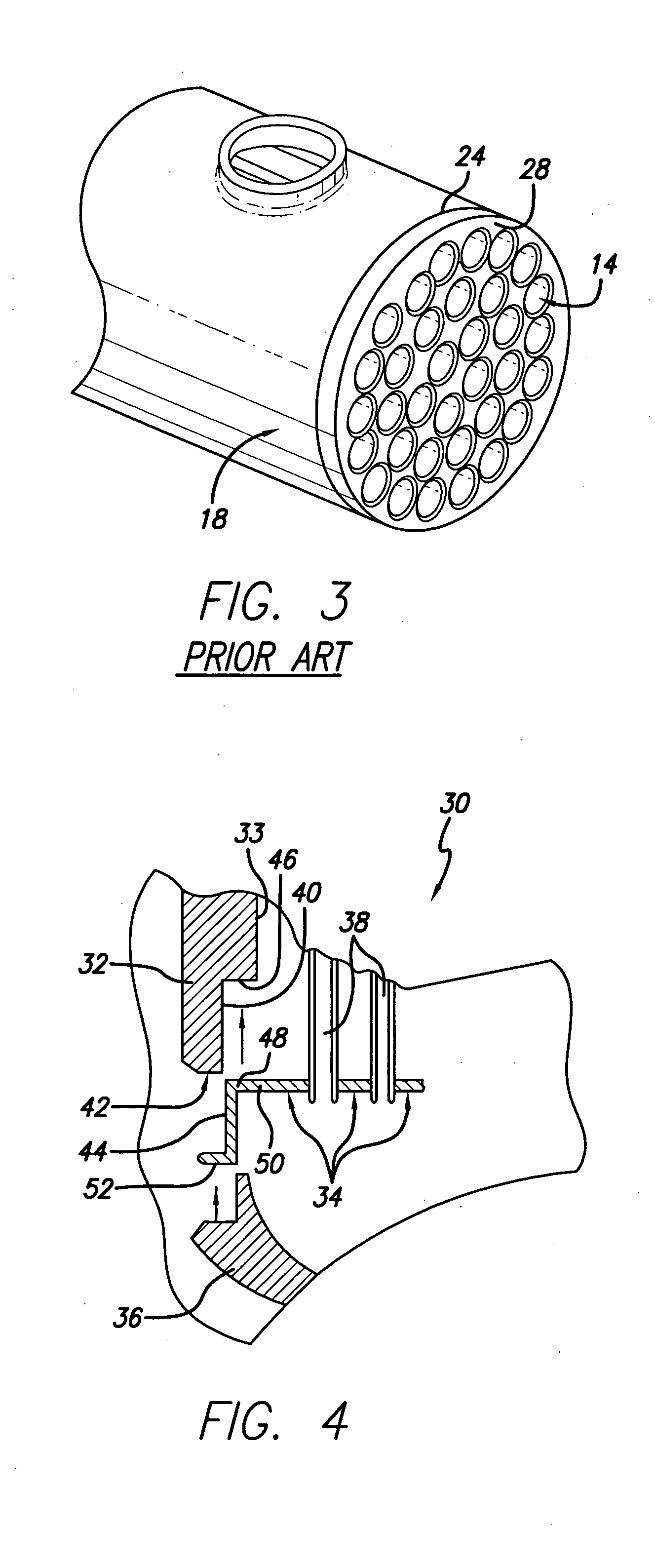
[0019] The present invention relates to heat exchangers used for reducing the temperature of an entering gas or fluid stream. The particular application for the heat exchangers of the present invention is with vehicles and, more particularly, to cool an exhaust gas stream from an internal combustion engine. However, it will be readily understood by those skilled in the relevant technical field that the heat exchanger configurations of the present invention described herein can be used in a variety of different applications. Generally, the invention constructed in accordance with the principles of this invention, comprises a heat exchanger including header plate and shell sections that are specially designed to cooperate with one another to form a nested attachment junction providing a braze joint of sufficient length therebetween to resist and protect against unwanted leakage.

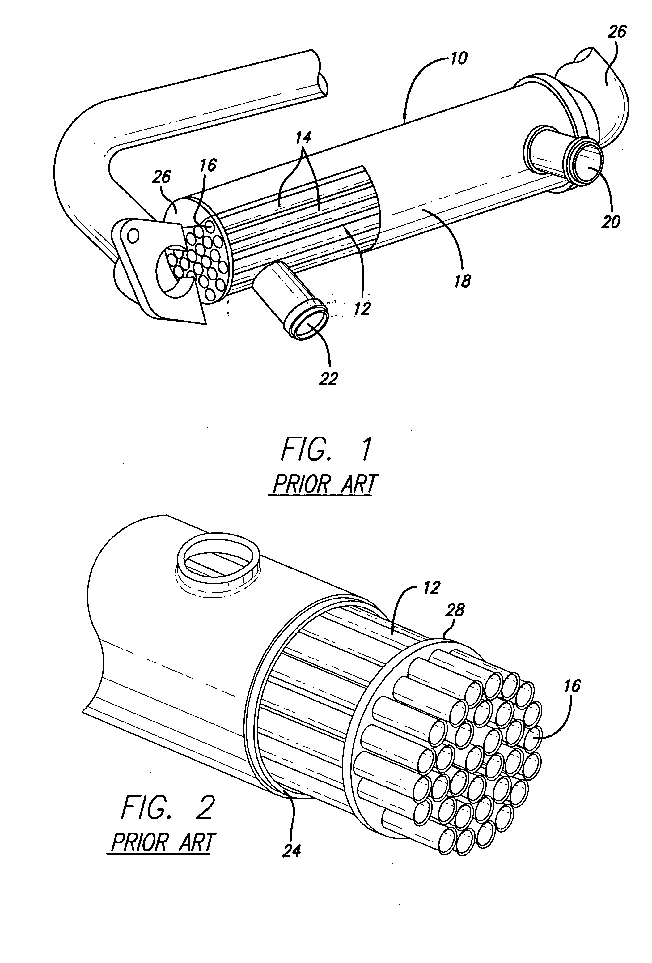
[0020] Referring to FIG. 3, conventional shell and tube heat exchangers comprise a header plate 28 having a...


PUM


Abstract

Heat exchangers of this invention include a shell having an inner chamber defined by an inside wall surface, and having at least one opening adjacent an end of the shell. A tube bundle comprising a plurality of assembled together tubes are disposed within the inner chamber. A header plate is attached to the tubes and is positioned adjacent an end of the tube bundle. The header plate includes an outside diameter that fits within the shell inside wall surface to provide a nested attachment junction therebetween. The header plate and shell are fixedly connected to one another by use of a braze joint formed by the placement of brazing material between the interfacing header plate and the shell surface sections. A tank is attached to the shell adjacent the shell end.

Description

FIELD OF INVENTION [0001] This invention relates generally to the field of heat exchangers and, more particularly, to heat exchangers that are specifically configured having one or more internal passages disposed within a surrounding body, and comprising a specifically configured attachment member for attaching the internal passages within the body. BACKGROUND OF THE INVENTION [0002] The present invention relates to heat exchangers that are generally configured comprising a number of internal fluid or gas passages disposed within a surrounding body. In an example embodiment, the internal passages are designed to accommodate passage of a particular fluid or gas in need of cooling, and the body is configured to accommodate passage of a particular cooling fluid or gas used to reduce the temperature of the fluid or gas in the internal passage by heat transfer through the structure of the internal passages. A specific example of such a heat exchanger is one referred to as a shell and tub...

Claims


Application Information

Patent Timeline
Patent Type & Authority Applications(United States)
IPC IPC(8): F28F9/02
CPCF02M25/0737Y02T10/121F28F9/0219F02M26/32
Inventor DILLEY, ROLAND L.BELDAM, RICHARD PAUL
Owner HONEYWELL INT INC
Why Eureka
Try Eureka