Retaining system for securing a cutting tool to a support block

a technology of retaining system and cutting tool, which is applied in the direction of cutting machine, cutting machine, earthwork drilling and mining, etc., can solve the problems of limited rotation speed of the mentioned drum, endangering people and structures in the vicinity of the operation, etc., and achieves the effect of promoting increased productivity, easy manufacturing, and high tip speed of the cutting tool

Inactive Publication Date: 2005-06-16
RIVER CITY MFG
View PDF13 Cites 21 Cited by
  • Summary
  • Abstract
  • Description
  • Claims
  • Application Information

AI Technical Summary

Benefits of technology

[0007] Yet another object of the present invention is to provide an improved retaining system for securing a cutting tool to a support block that allows easy removal of the cutting tool from the support block.
[0008] Still another object of the present invention is to provide an improved retaining system for securing a cutting tool to a support block that requires simple tools to remove the cutting tool from the support block.
[0009] Yet another object of the present invention is to provide an improved retaining system for securing a cutting tool to a support block that is easy to manufacture.
[0010] A further obje

Problems solved by technology

Typically, the aforementioned drum is limited in rotation speed due to unreliable clips or fittings holding the cutting tool into the support block.
A problem in increasing rotation speeds utilizing ret

Method used


Image

  • Retaining system for securing a cutting tool to a support block
  • Retaining system for securing a cutting tool to a support block
  • Retaining system for securing a cutting tool to a support block

Examples


Embodiment Construction

[0021] Prior to proceeding to a much more detailed description of the present invention, it should be noted that identical components which have identical functions have been identified with identical reference numerals throughout the several views illustrated in the drawing figures for the sake of clarity and understanding of the invention.

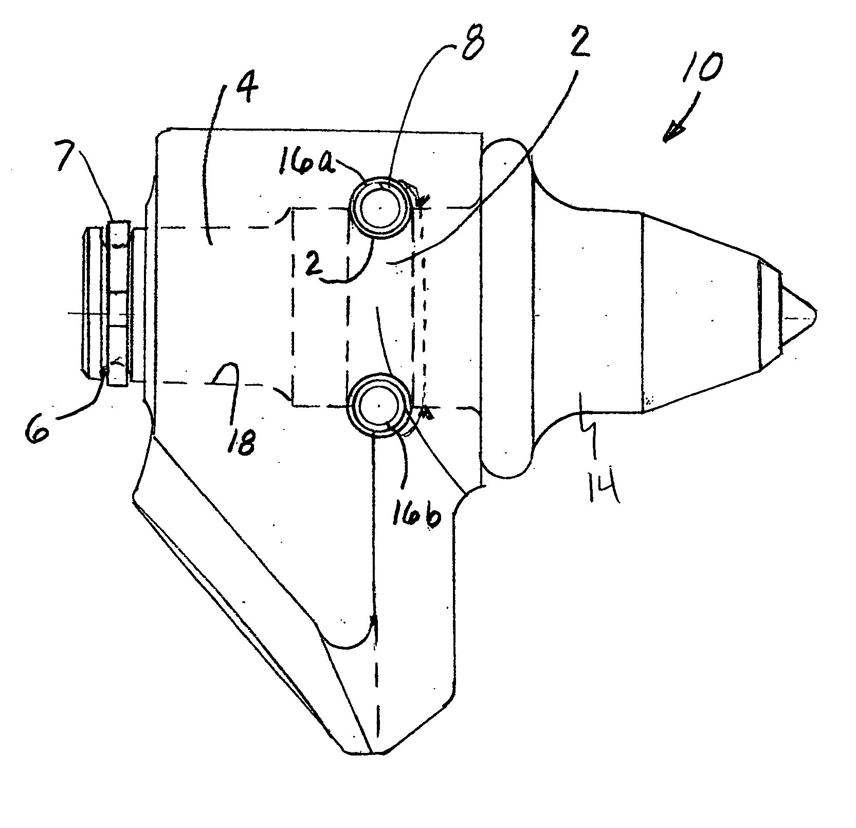
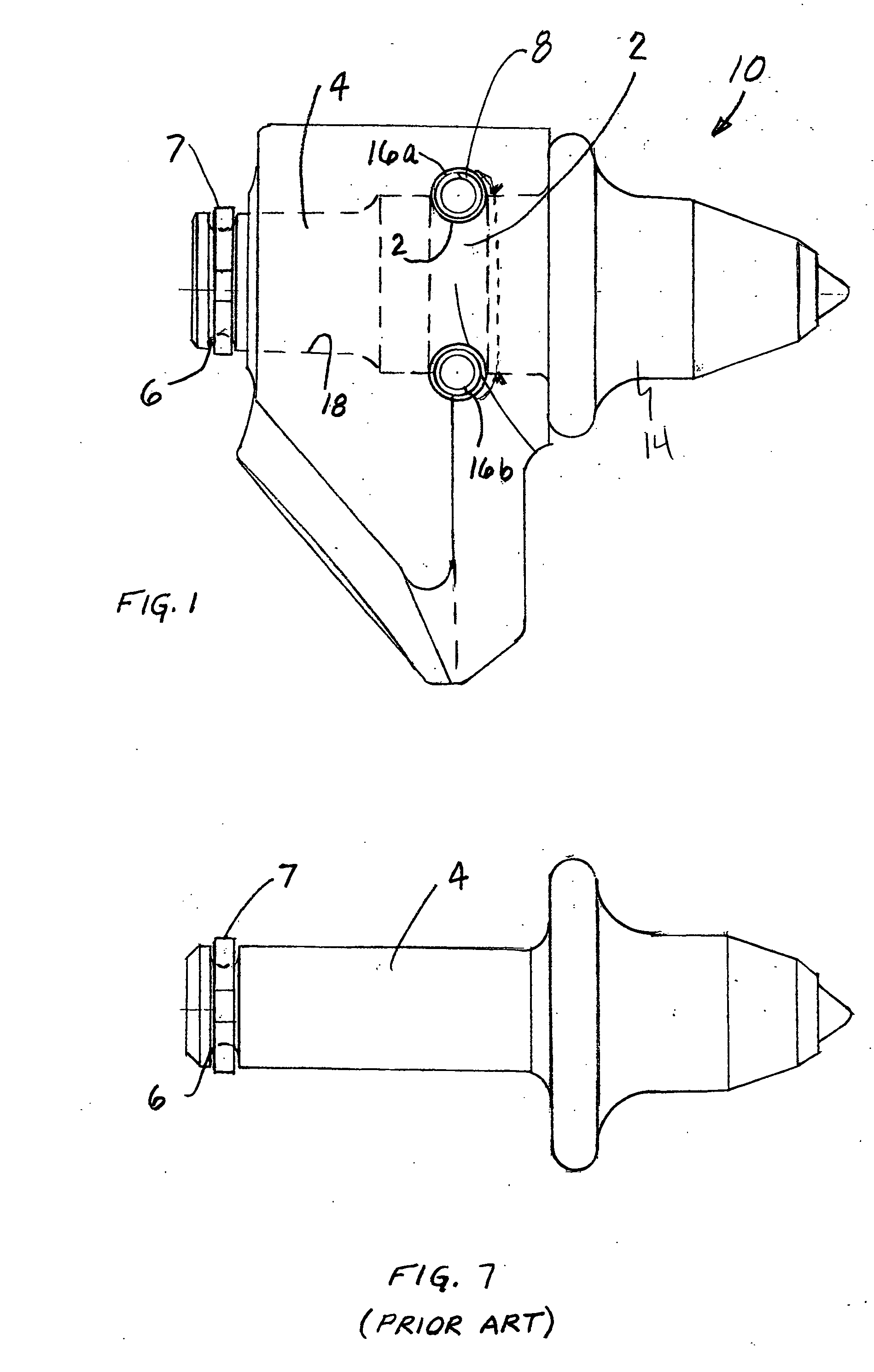
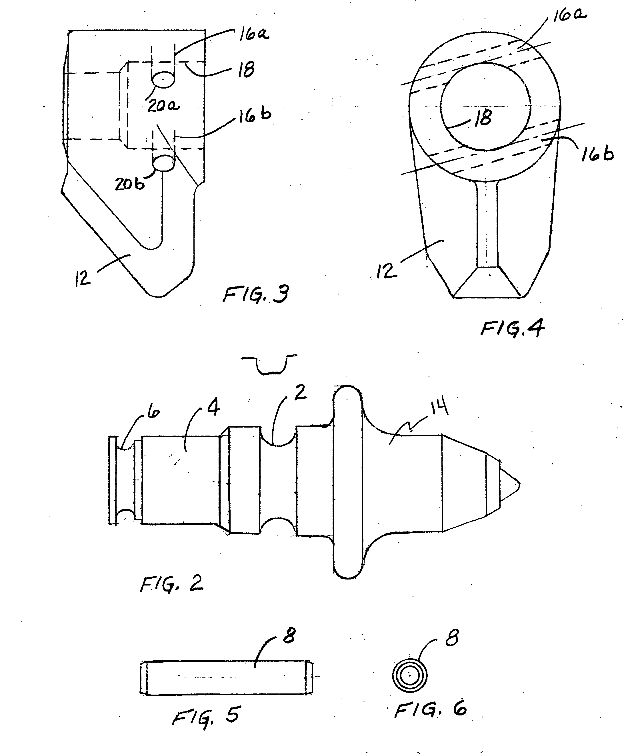
[0022] Referring initially to FIGS. 1 and 2, a retaining system is generally indicated by reference numeral 10, the retaining system 10 includes a cutting tool 14 and a support block 12. There is at least one groove 2 having a predetermined shape, formed in an outer surface of a shank portion 4 of the cutting tool 14, groove 2 being formed in a direction transverse to a longitudinal axis of shank 4. Preferably such predetermined shape is oblong.

[0023] In FIG. 1 and FIG. 7 the shank portion 4 further includes a circumferential groove 6 formed closely adjacent an end of shank portion 4 for receiving a washer like member 7 to further retain the cu...


PUM


Abstract

The present invention provides an improved retaining system for securing a cutting tool to a support block. The retaining system includes at least one groove, having a first predetermined shape, formed in an outer surface of a shank portion of the cutting tool. The groove is formed in a direction transverse to a longitudinal axis of the shank. There is at least one groove, having a second predetermined shape, formed in a surface of a bore formed through an axis of the support block for receiving the shank portion of the cutting tool. The at least one groove formed in the outer surface of the shank portion of the cutting tool is radially opposed to the at least one groove formed in the surface of the bore formed through the axis of the support block when the shank portion is inserted into the bore of the support block. The final essential element of the retaining system is at least one pin member engageable with each of at least one groove formed in the outer surface of such shank portion of the cutting tool and the at least one groove formed in the surface of the bore formed through the axis of the support block for securing the cutting tool to the support block.

Description

FIELD OF THE INVENTION [0001] The present invention relates, in general, to cutting tools and, more particularly, this invention relates to an improved retaining system for retaining such cutting tools in their support blocks. BACKGROUND OF THE INVENTION [0002] Prior to the conception and development of the present invention, cutting tool assemblies have been in widespread use. These cutting tool assemblies are used, typically, in mining and in the surface milling of roads. The cutting tool usually carries a hardened tip for increased tool life and is rotatably mounted into a support block. The support blocks are either bolted or welded onto a drum or other carrier, which in turn is driven to engage the cutting tools forcibly into whatever material is chosen to be addressed by the machinery. [0003] Typically, the aforementioned drum is limited in rotation speed due to unreliable clips or fittings holding the cutting tool into the support block. To increase performance of milling in ...

Claims


Application Information

Patent Timeline
IPC IPC(8): E21C35/193
CPCE21C35/1933
Inventor ERICKSON, ROBERT W.
Owner RIVER CITY MFG
Why Eureka
Try Eureka