Electric trailer brake controller

Active Publication Date: 2005-06-16
HAYES BRAKE CONTROLLER
View PDF37 Cites 49 Cited by
  • Summary
  • Abstract
  • Description
  • Claims
  • Application Information

AI Technical Summary

Benefits of technology

[0017] The invention also contemplates that the controller includes a programmable current sensing power switch that is adapted to be connected between a power supply and a set of trailer brake coils. The power switch is connected to an output pin of the microprocessor and responsive to the brake control signal to supply a current that is a function of the brake control signal to the trailer brake coils. The power switch is also connected to a current feedback port of the microprocessor and the microprocessor is operative to monitor

Problems solved by technology

However, know controllers tend to be non-linear devices and usually

Method used


Image

  • Electric trailer brake controller
  • Electric trailer brake controller
  • Electric trailer brake controller

Examples


Embodiment Construction

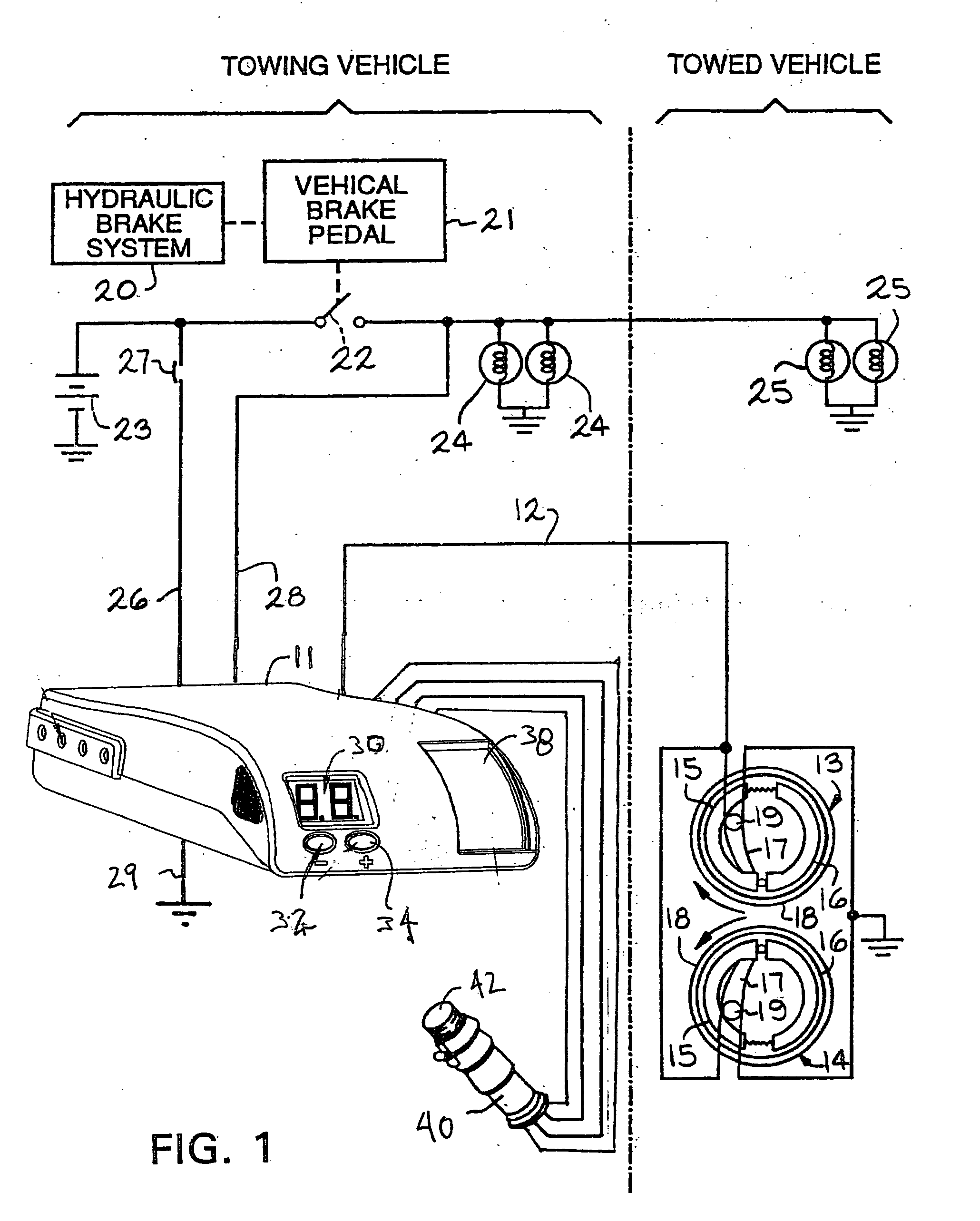
[0037] Referring now to the drawings, there is shown in FIG. 1 a schematic diagram illustrating an electric brake system for a towed vehicle (not shown), shown generally at 10, which utilizes an electronic brake controller 11 embodying the principles of the present invention. The brake controller 11 is typically located in a towing vehicle (not shown), usually being mounted beneath the towing vehicle dashboard. When actuated, the controller 11 functions to supply an electric current through a first line 12 to energize electric brakes 13 and 14 which brake the wheels of the towed vehicle (not shown).

[0038] The electric brakes 13 and 14 each include a pair of brake shoes 15 and 16 which, when actuated by a lever 17, are expanded into contact with a brake drum 18 for braking the wheels of the towed vehicle. A separate electromagnet 19 is mounted on an end of each of the brake actuating levers 17. Each electromagnet 19 is positioned to abut the generally flat side of the brake drum 18....


PUM


Abstract

A micro processor based electric brake controller includes a multi-axis accelerometer that senses deceleration of a towing vehicle along a plurality of directional axes. The controller also includes a microprocessor that is responsive to the sensed decelerations to supply power to trailer brakes that is a function of the deceleration.

Description

CROSS REFERENCE TO RELATED APPLICATIONS [0001] This application is a Continuation-in-Part Application of U.S. Utility patent application Ser. No. 10 / 962,163, filed Oct. 8, 2004 and claims the benefit of U.S. Provisional Application No. 60 / 509,974, filed Oct. 9, 2003, the disclosure of which is incorporated herein by reference.BACKGROUND OF INVENTION [0002] This invention relates in general to controllers for electric wheel brakes used on trailers and in particular to an improved controller for such electric wheel brake controllers. [0003] Towed vehicles, such as recreational and utility trailers that are towed by automobiles and small trucks, are commonly provided with electric wheel brakes. The electric wheel brakes generally include a pair of brake shoes which, when actuated, frictionally engage a brake drum. An electromagnet is mounted on one end of a lever to actuate the brake shoes. When an electric current is applied to the electromagnet, the electromagnet is drawn against the...

Claims


Application Information

Patent Timeline
IPC IPC(8): B60T7/20B60T13/74
CPCB60T13/74B60T7/20
Inventor ROBERTSON, CHARLES L.
Owner HAYES BRAKE CONTROLLER
Why Eureka
Try Eureka