Electric-field meter having current compensation

a technology of electric field meters and current compensation, which is applied in the installation of lighting conductors, electrostatic field measurements, instruments, etc., can solve the problems of high cost of commercial field meters currently available, high electrical power requirements, and well known natural hazards of lighting

Inactive Publication Date: 2005-06-16
THE BOARD OF RGT UNIV OF OKLAHOMA
View PDF54 Cites 6 Cited by
  • Summary
  • Abstract
  • Description
  • Claims
  • Application Information

AI Technical Summary

Problems solved by technology

Lightning is a well known natural hazard.
The cost of commercial field meters currently available is high, they have great electrical power requirements, and they usually need frequent preventive and periodic maintenance.
These disadvantages preclude widespread application of commercially available field meters.
More specifically, the prior art electric-field meters suffer from at least three problems which make their wide spread use generally too costly.
These three factors are relatively high power consumption, difficult calibration procedure, and stringent requirements for frequent maintenance.
In the prior art, the cleaning operation is difficult because the prior art electric-field meters require extensive and complex disassembly of the instrument to remove electrodes and thereby clean insulators and electrodes.
The disassembly of the prior art electric-field meters for electrode and insulator cleaning thus requires a highly skilled technician adding considerably to the on-going expenses associated with the electric-field meter.
Commercial field meters typically consume tens to hundreds of watts of electrical power.
Such high power consumption precludes or discourages application of commercial field meters on most of the existing remote, solar-powered weather stations where electrical power is severely limited.
This process also typically involves a skilled technician and involves risks of opening and improperly closing sealed enclosures in the field.
Prior-art field meters suffer from two types of uncorrected errors that change with time, temperature, humidity and atmospheric pollutants.
Prior-art field meters also suffer from variations in leakage current at the charge-amplifier input due to conduction across insulators associated with the sense electrode and the circuitry used for charge measurement.
For prior-art field meters at the place and time of manufacture, the average leakage current at the charge-amplifier input is typically negligible but it can worsen overtime with various atmospheric conditions.
The average leakage current in prior-art field meters is an unknown variable that can degrade an instrument to a state of improper operation without warning.
Uncorrected changes in average leakage currents may cause measurement errors in the electric field, possibly leading to improper assessment of atmospheric electrical threats.
Field meters that suffer from unknown and uncorrected zero offsets and average leakage currents do not always provide information of high quality over long periods of use and such field meters typically require labor intensive testing, adjusting and cleaning at times that have to be determined empirically.

Method used


Image

  • Electric-field meter having current compensation
  • Electric-field meter having current compensation
  • Electric-field meter having current compensation

Examples


Embodiment Construction

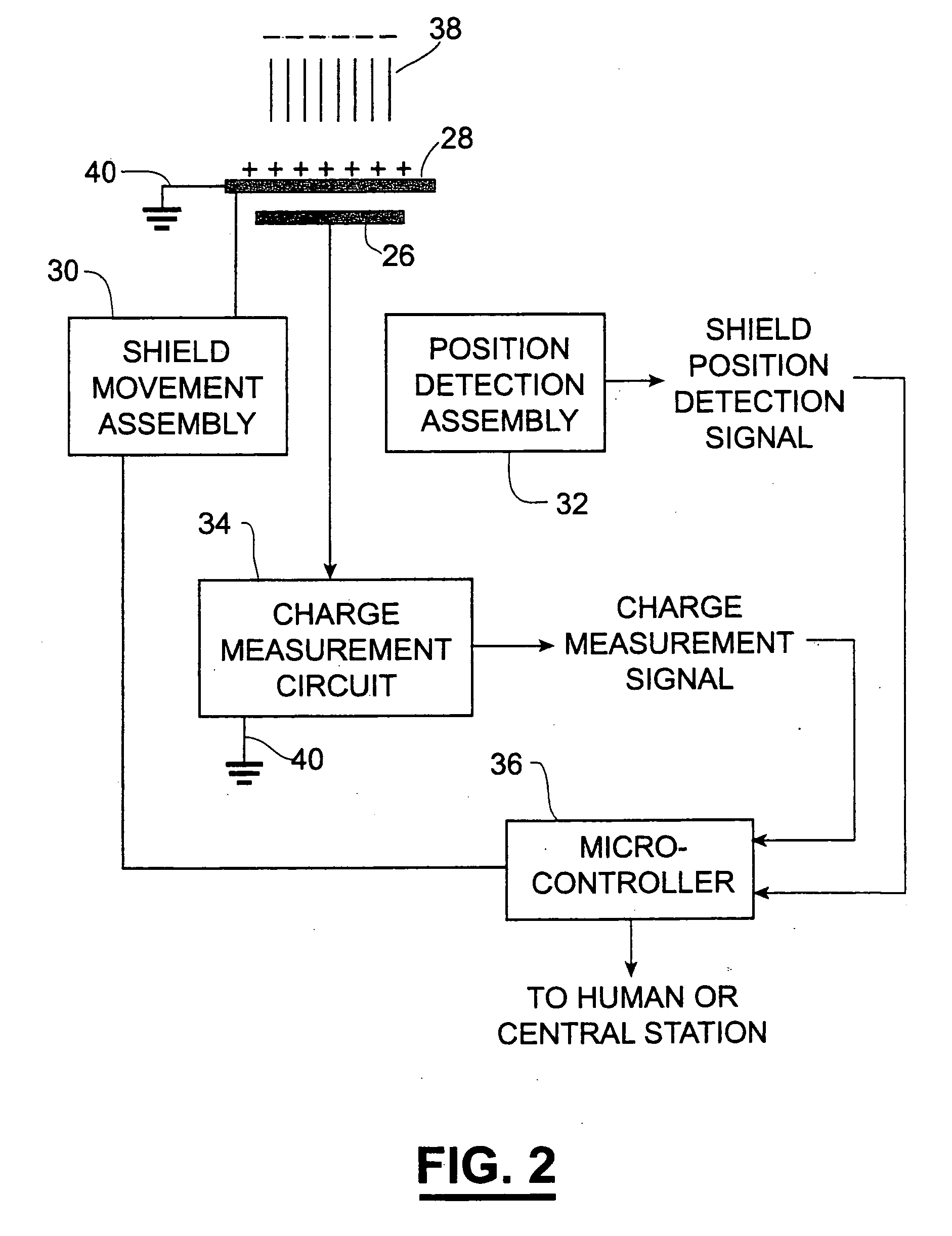
[0032] The present invention is directed to improvements in electric-field meters to allow more cost effective and reliable monitoring of atmospheric electrification at single or multiple remote stations. The electric-field meter of the present invention exploits the physical principle that charge is induced on a conductor placed in an electric field. By alternately covering and exposing a conducting and properly insulated electrode assembly, induced charge flows back and forth to the successively exposed, then unexposed, electrode assembly through charge-sensing electronic circuits. The electronic signal produced is indicative of (e.g., proportional to) the applied electric field at the electrode assembly when exposed. Thus, the electric-field meters can be used for measuring a magnitude and / or a polarity of a steady or changing electric field.

[0033] The electric-field meters of the present invention can be used either individually or as a part of a network for research orfor wide...


PUM


Abstract

An electric-field meter provided with a housing, an electrode assembly, a shield assembly, a movement assembly, a position detection assembly, a charge measurement circuit, and a leakage current compensation circuit. The electric-field meter can be characterized as a field mill, an induction voltmeter, an electrostatic fluxmeter or an agrimeter. The electrode assembly is selectively exposed to the electric field. The shield assembly alternately covers and exposes the electrode assembly to the electric field. The movement assembly has a source of motive force and a linkage operably connected to one of the shield assembly and the electrode assembly for alternately covering and exposing the electrode assembly to the electric field. The charge measurement circuit receives charge on the electrode assembly. The charge measurement circuit provides a charge detection signal indicative of the charge induced on the electrode assembly as the electrode assembly is selectively exposed to the electric field. A current compensation circuit is provided for offsetting an average leakage current at the input of the charge measurement circuit.

Description

CROSS-REFERENCE TO RELATED APPLICATIONS [0001] This patent application is a continuation-in-part of U.S. Ser. No. 10 / 094,942, filed Mar. 14, 2002, which claims priority to the provisional patent application identified by U.S. Ser. No. 60 / 275,763, filed on Mar. 14, 2001, the entire contents of U.S. Ser. Nos. 10 / 094,942 and 60 / 275,763 are hereby expressly incorporated in their entirety by reference.STATEMENT REGARDING FEDERALLY SPONSORED RESEARCH AND DEVELOPMENT [0002] Portions of the invention may have been funded under NSF Grant ATM-9724594.BACKGROUND OF THE INVENTION [0003] Lightning is a well known natural hazard. Every year in the United States, lightning kills approximately one hundred people and injures on the order of a thousand. Approximately 50 million cloud-to-ground lightning discharges occur each year in the U.S. Damage to equipment and disruption of commercial and industrial operations is measured in billions of dollars. For these reasons, and for many safety-related and...

Claims


Application Information

Patent Timeline
Patent Type & Authority Applications(United States)
IPC IPC(8): G01R29/12
CPCG01R29/12H02G13/60H02G13/00
Inventor SWENSON, JODY A.BEASLEY, WILLIAM H.BYERLEY, LEON G.BOGOEV, IVAN G.
Owner THE BOARD OF RGT UNIV OF OKLAHOMA
Why Eureka
Try Eureka