Method and device for detecting touch pad input

a technology of touch pad input and detection method, which is applied in the direction of instruments, computing, electric digital data processing, etc., can solve the problems of affecting the optical transparency of display, and affecting the display of text or images

Inactive Publication Date: 2005-06-16
NOKIA CORP
View PDF8 Cites 187 Cited by
  • Summary
  • Abstract
  • Description
  • Claims
  • Application Information

AI Technical Summary

Problems solved by technology

When a user presses the pad, the layers are caused to make contact with each other at the pressing point, thereby interrupting the current in the electrode grid.
When the touch pad is also used as an information display or an image display, the electrodes positioned on top of a touch pad may affect the optical transparency of display and / or distort the displayed text or image.
Furthermore, some touch pads can be damaged by having dirt or scratches on the touch pad surface.
While a touch pad using this surface wave technology does not affect the optical quality of the display, it is costly to produce.

Method used


Image

  • Method and device for detecting touch pad input
  • Method and device for detecting touch pad input
  • Method and device for detecting touch pad input

Examples


Embodiment Construction

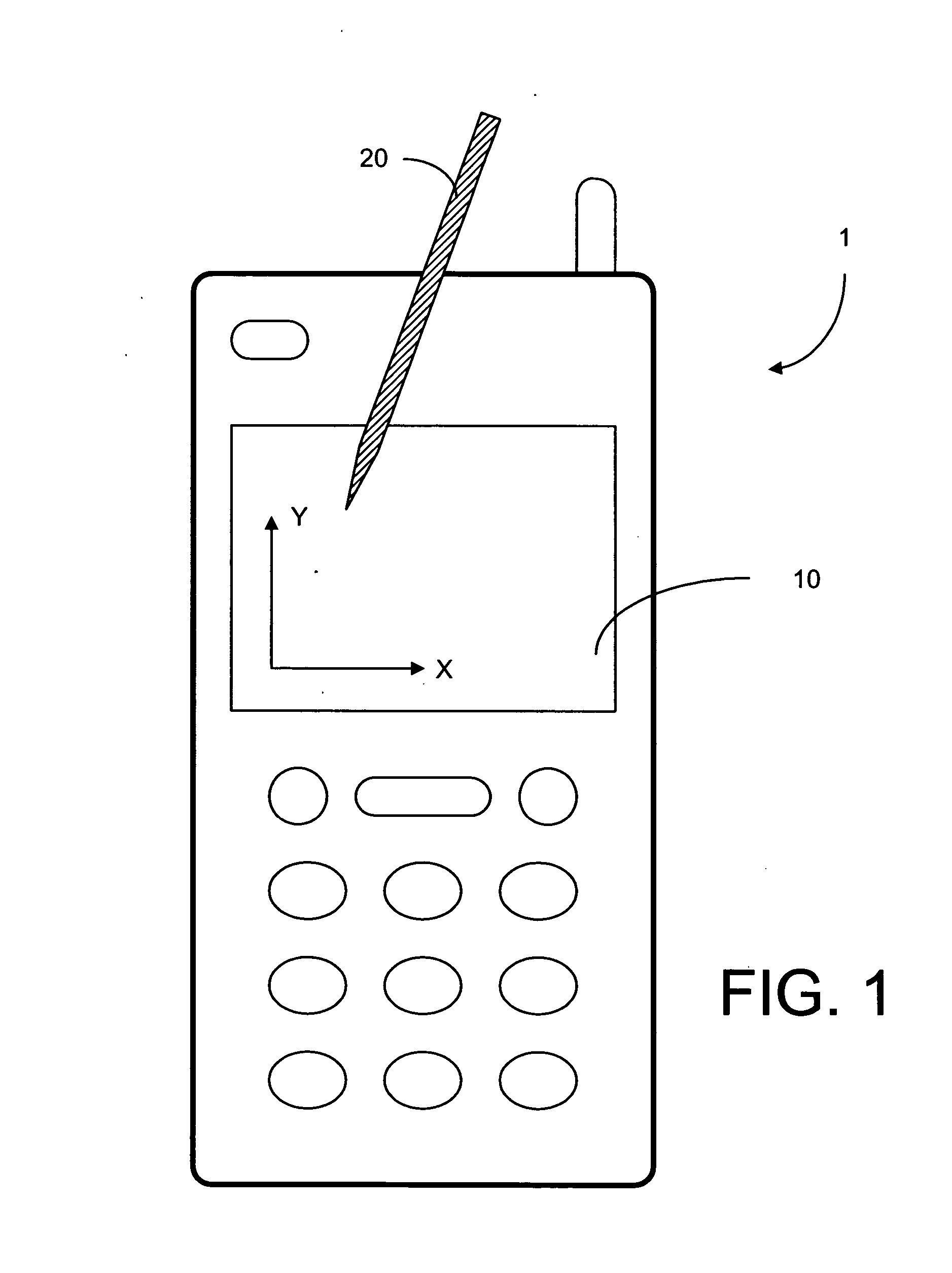
[0060]FIG. 1 is a schematic representation of a portable electronic device. The portable electronic device 1, as shown in the figure, can be a mobile terminal, a communicator device, a personal digital assistance (PDA), or the like. The electronic device 1 has a touch screen 10 to allow a user to use an object such as a stylus 20, a finger or any suitable object to input information in the electronic device 1. For example, if the touch screen 10 has one or more soft buttons to allow the user to execute a function, the user can use the object 20 to select a desired soft button on the touch screen 10. The user can also use the object to write alphabet characters, to make a drawing and so forth. The touch screen 10 has means to detect the position and / or movement of the touching object 20 in both X and Y directions.

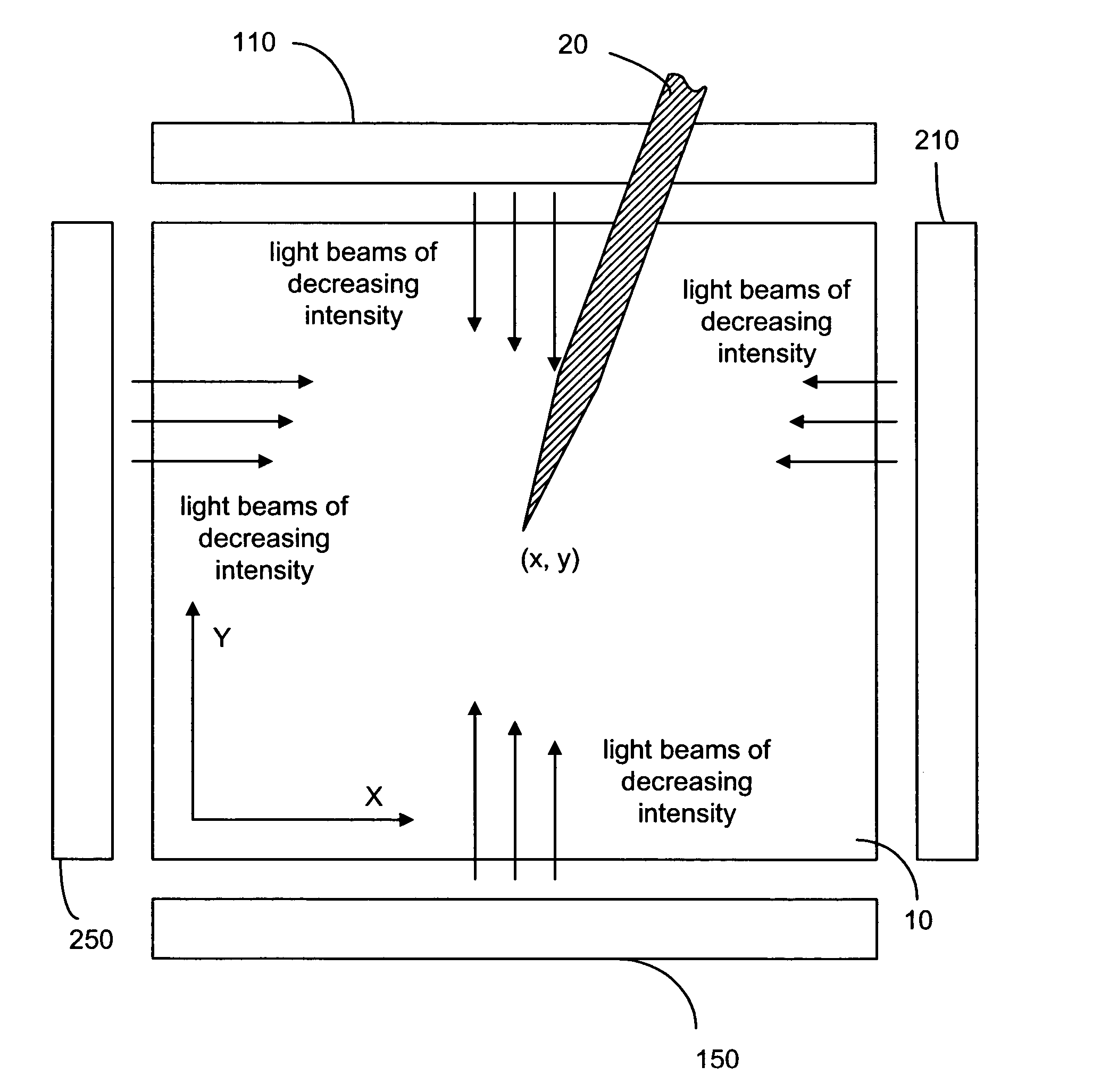
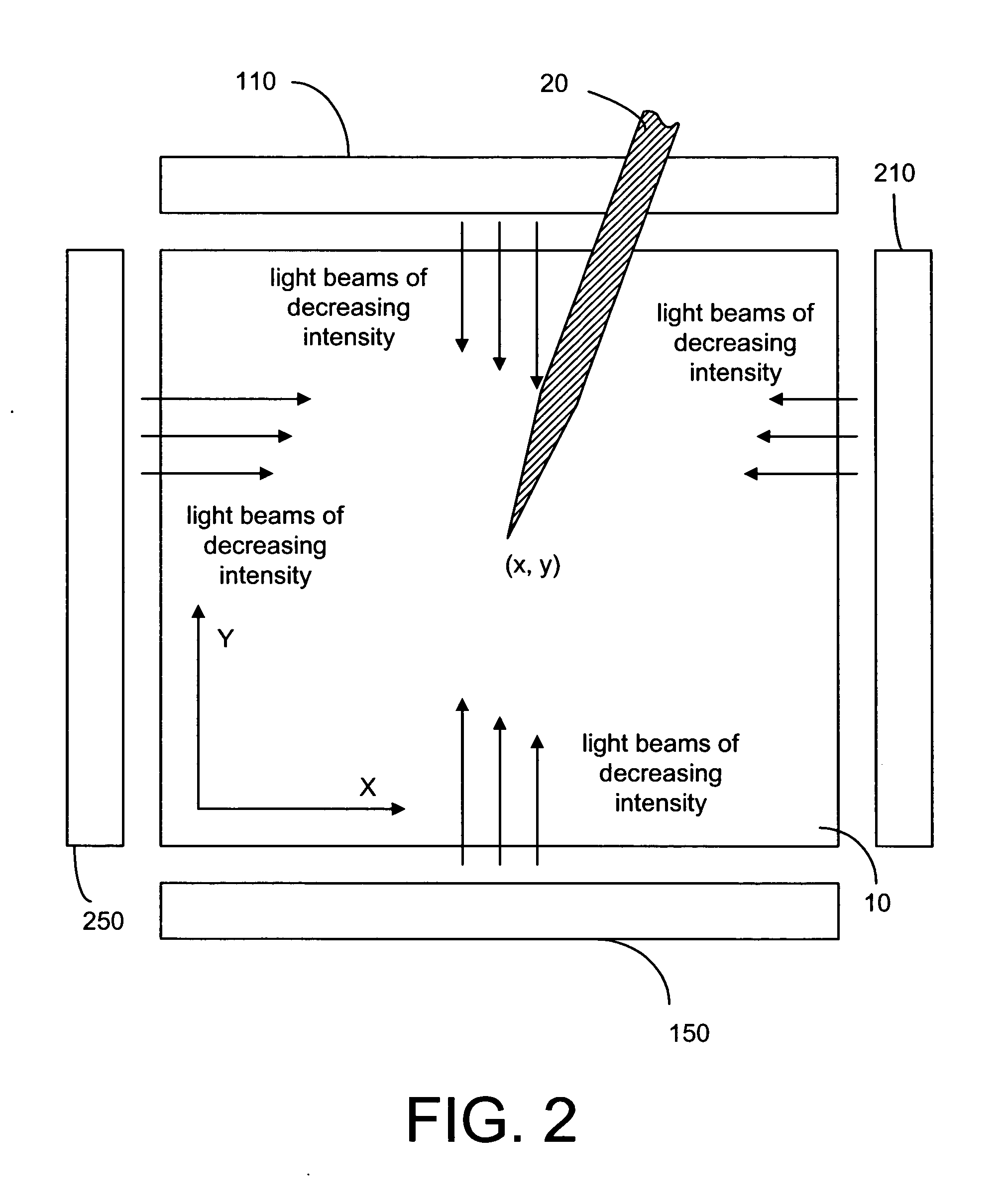
[0061] As shown in FIG. 2, the touch screen 10 has two optical emitter / detector systems 110 and 150 to detect the position and / or motion of the touching object 20 in the X ...


PUM


Abstract

A method and system for determining the location of an object touching a touch pad. A light source is used to provide a light beam and a plurality of reflecting surfaces are disposed along an edge of the touch pad to partially reflect the light beam in order to provide a light sheet over the touch pad, such that the reflected intensity varies monotonously along the edge. A detector structure is disposed on the opposite edge to measure the light intensity of the light sheet, part of which is blocked when the object touches the touch pad. The reduction in the measured light intensity is used to calculate the location of the touching object in one direction. A second light sheet and a corresponding detector structure can be used to determine the location of the touching object in a different direction.

Description

FIELD OF THE INVENTION [0001] The present invention relates generally to a touch sensitive device in an electronic device or a wireless telecommunication terminal. BACKGROUND OF THE INVENTION [0002] A touch pad is usually defined as a touch-sensitive user interface area in an electronic device, which allows a user to input information or a command to the device by pressing the touch sensitive area. The touch pad can be used as a keypad having a designated functionality. For example, a touch pad can be used as an on / off switch and the user can turn the electronic device on or off by pressing the touch sensitive area. The touch pad can have several selectable functions. For example, the touch pad can be used as a keyboard having a plurality of soft-keys of different functions to allow the user to enter or select one function at a time. [0003] In some touch pads, it is required to press the pad surface in order to deform it. In such a touch pad, several layers of material, separated by...

Claims


Application Information

Patent Timeline
Patent Type & Authority Applications(United States)
IPC IPC(8): G06F3/042G09G5/00
CPCG06F3/0421
Inventor RYYNANEN, MATTI
Owner NOKIA CORP
Why Eureka
Try Eureka