Image reading unit and image forming apparatus comprising the same

a technology of image forming apparatus and reading unit, which is applied in the direction of electrographic process apparatus, instruments, optics, etc., can solve the problems of insufficient antistatic effect, inability to obtain sufficient antistatic effect, and stagnation of dust on document glass, so as to prevent the appearance of image stripes and prevent the stagnation of dus

Inactive Publication Date: 2005-06-16
CANON KK
View PDF10 Cites 21 Cited by
  • Summary
  • Abstract
  • Description
  • Claims
  • Application Information

AI Technical Summary

Benefits of technology

[0011] Accordingly, an object of the present invention is to provide an image reading unit capable of preventing stagnation of dusts on a document glass so as to prevent occurence of image stripes and an image forming apparatus comprising the same.
[0013] Moreover, the representative configuration of the image reading unit comprises a document feeding device for feeding a document, a transparent document guide for guiding the document fed by the document feeding device, an image reading device for reading the image on the document via the transparent document guide, and a conductive member for eliminating the charge of the transparent document guide, wherein the conductive member has a length same as or longer than the maximum document width to be read, and is conductive with the transparent document guide.

Problems solved by technology

In the conventional example, a problem is involved in that dusts such as toner particles, paper dusts, and rubber dusts occured by the document feeding operation are stagnated on the document glass.
In particular, in the case where the dusts are stagnated at the document reading position, a problem arises in that a stripe image is occured at the time of recording an image.
Moreover, since the conventional earth spring is provided in the document glass 516 longitudinal direction (document width direction) end part so that the distance between the static electricity generating area and the earth spring is long and the total resistance value is large, a sufficient antistatic effect cannot be obtained, and thus electrostatic attachment of the dusts G onto the document glass 516 cannot be prevented.

Method used


Image

  • Image reading unit and image forming apparatus comprising the same
  • Image reading unit and image forming apparatus comprising the same
  • Image reading unit and image forming apparatus comprising the same

Examples


first embodiment

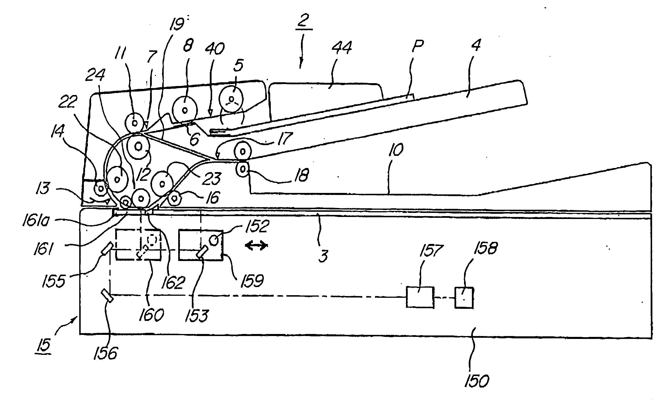
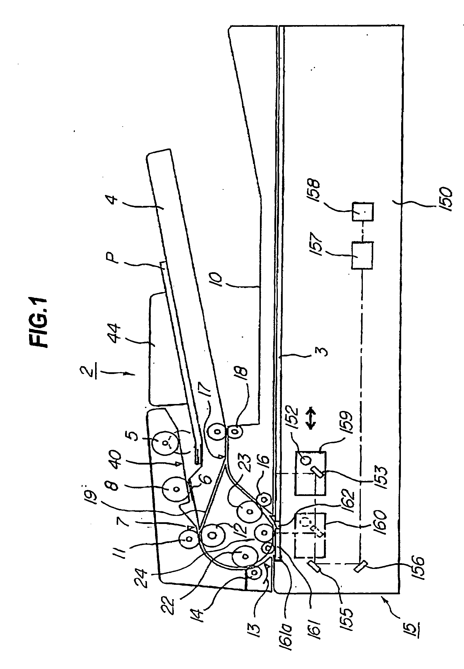
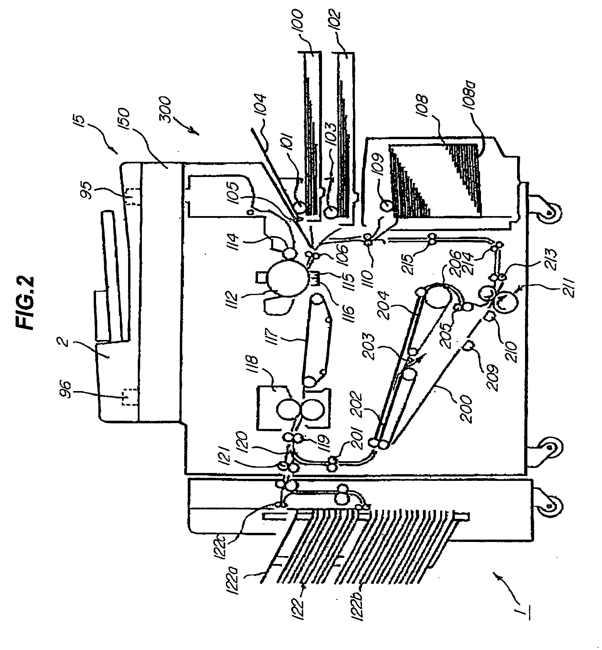
[0028] A first embodiment of an image reading unit according to the present invention and an image forming apparatus comprising the same will be explained with reference to the drawings. FIG. 1 is a cross sectional view of an image reading unit according to this embodiment. FIG. 2 is a configuration diagram of an image forming apparatus. FIG. 3 is an explanatory diagram of a driving system of a document feeding unit. FIG. 4 is a detailed diagram of a document reading part. FIG. 5 is a rear view of a document feeding unit for explaining the hinge mechanism. FIGS. 6 to 8 are an explanatory diagram of a hinge mechanism of a document feeding unit. FIG. 9 is a control block diagram of a document feeding unit. FIG. 10 is a control block diagram of a reading unit.

[0029] As shown in FIG. 2, the image forming apparatus 1 comprises a printer part 300 and an image reading unit 15.

(Explanation of the Printer Part)

[0030] The printer part 300 is an image forming apparatus main body using know...


PUM


Abstract

The representative configuration of an image reading unit according to the present invention and an image forming apparatus comprising the same is an image reading unit comprising a document feeding unit, a lamp and a mirror for reading out the image on a document, a flow reading platen provided between the document feeding unit, and the lamp and the mirror for guiding the document while sliding the same against the surface, and an aluminum sheet for grounding the flow reading platen, wherein the aluminum sheet is conductive with the flow reading platen on the document feeding direction upstream side with respect to the document reading position for reading the image in the substantially entire document width by the lamp and the mirror.

Description

BACKGROUND OF THE INVENETION [0001] 1. Field of the Invention [0002] The present invention relates to an image reading unit for reading out an image on a sheet material (document) comprising a document feeding unit for automatically feeding the sheet material (document) with the image recorded, used for a scanner, a copying machine, a printer, a facsimile equipment, or the like, and an image forming apparatus comprising the same. [0003] 2. Description of the Related Art [0004] Conventionally, there is an image reading unit comprising a document feeding unit (hereinafter, it is referred to as the ADF (auto document feeder)) such as a double side compatible automatic document feeding unit used for an image forming apparatus such as a digital copying machine. According to the image reading unit used for the digital copying machine comprising an ADF of this kind, in the case where of copying a document in the ADF, reading means is moved to a set position provided below the ADF by a moto...

Claims


Application Information

Patent Timeline
Patent Type & Authority Applications(United States)
IPC IPC(8): G03G15/00H04N1/00H04N1/04H04N1/10H04N1/12H04N1/193
CPCG03G15/605G03G2215/00189H04N1/00909H04N1/00976H04N2201/0081H04N1/1013H04N1/1215H04N1/193H04N1/0464
Inventor YAMANAKA, YUJITERAE, TAKUYA
Owner CANON KK
Why Eureka
Try Eureka