Plasma arc torch cutting component with optimized water cooling

a technology of cutting components and plasma arc torch, which is applied in the field of high-temperature processing of metallic materials, can solve the problems of overheating of the nozzle, local melting of the nozzle material, and oxidation erosion of the nozzle material, and achieve the effect of reducing fluid flow stagnation

Active Publication Date: 2009-01-29
HYPERTHERM INC
View PDF17 Cites 27 Cited by
  • Summary
  • Abstract
  • Description
  • Claims
  • Application Information

AI Technical Summary

Benefits of technology

[0029]In another aspect, the invention relates to a nozzle for use in a fluid-cooled plasma torch. The nozzle can include a body having an outer perimeter that partially defines a fluid channel, the body can include an end face wherein the end face is perpendicular to a longitudinal axis of the component. In some embodiments a groove extends at least partially through the end face and an elastomeric seal can be disposed within the groove to provide a barrier between a plasma gas flow and the fluid channel. The groove and seal can provide the fluid seal between the plasma gas region of the torch and the water cooled region of the torch. In some embodiments, the groove and seal disposed in the end face of the nozzle can provide a protective barrier that reinforces and supplements a sealing component that is disposed in an exterior surface of the nozzle.
[0034]In a further aspect of the invention, a method of cooling a plasma torch component comprises exchanging heat from a first torch component with an adjacent torch component through a conductive contact portion. In some embodiments the method can include flowing a cooling fluid through a cooling channel having a curvilinear surface, the curvilinear surface configured to prevent fluid stagnation. In some embodiments the method can also include providing a barrier comprising a sealing component between the conductive contact portion and the cooling channel.
[0043]Another aspect of the invention includes a method of cooling a plasma torch component. The method can include exchanging heat from a shield with an adjacent torch component through a conductive contact portion, flowing a cooling fluid through a cooling channel having a curvilinear surface, the curvilinear surface configured to prevent fluid stagnation, and providing a barrier comprising a sealing component between the conductive contact portion and the cooling channel.
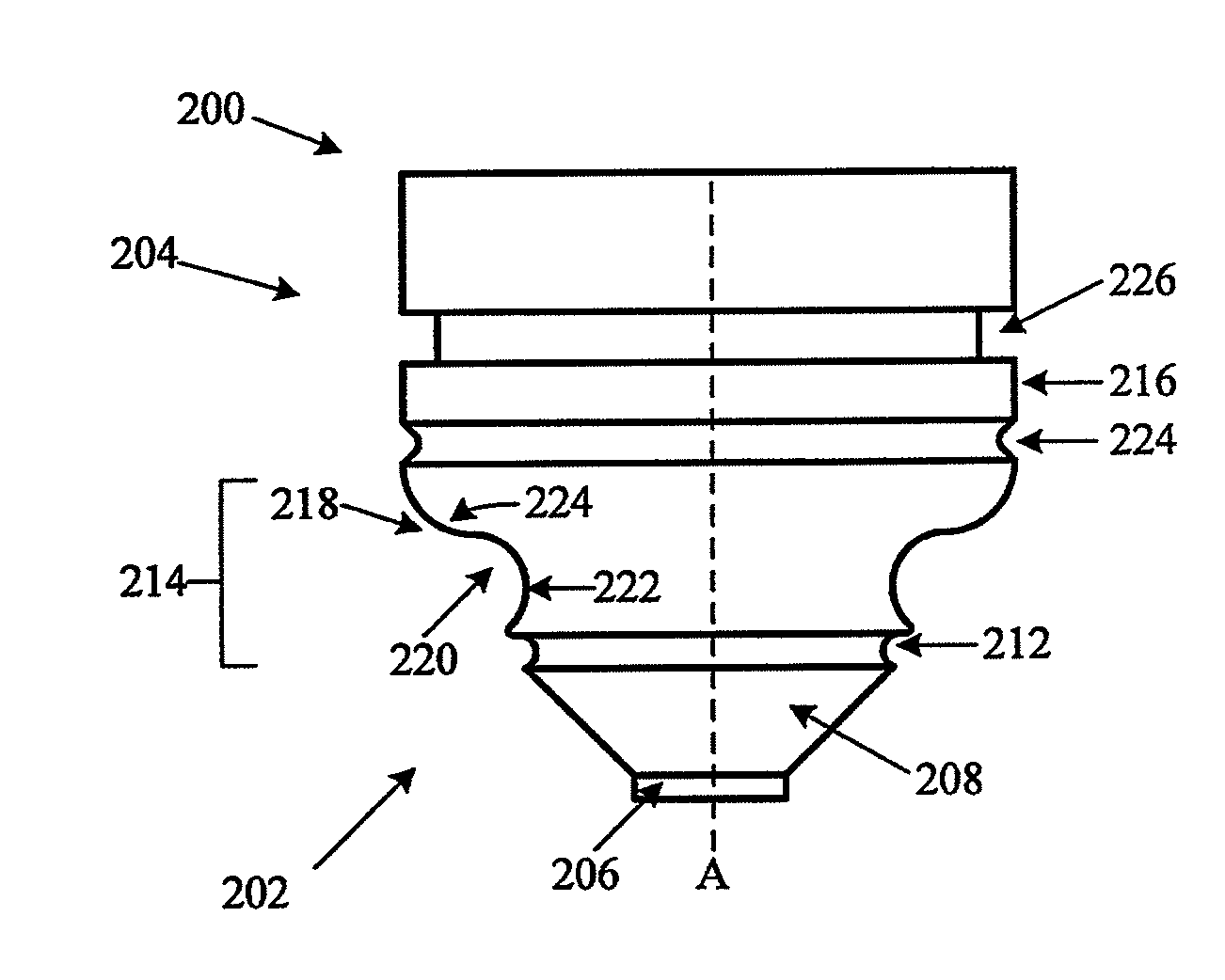
[0050]Any of the aspects above can include one or more of the following features. A cooling structure can be at least partially disposed within a nozzle or a shield. And in some embodiments the cooling structure is at least partially disposed within the retaining cap. In some embodiments a channel is disposed within the nozzle of a plasma arc torch. In some embodiments a channel is disposed within the shield of a plasma arc torch. And in some embodiments the channel intrudes into a wall thickness of the nozzle. And in some embodiments the channel is configured to reduce fluid flow stagnation.

Problems solved by technology

The higher heat flux can lead to overheating of the nozzle, oxidation erosion of the nozzle material (e.g., copper), or local melting of the nozzle material.
Damage to the nozzle from overheating and double-arcing can cause the plasma jet or arc to widen and / or diverge due to less constriction by the nozzle shape, resulting in defects in cut quality such as increased angle variation, wide kerf, and excessive dross.
Generally, cooling a nozzle with a gas flow is weaker or less effective than cooling the nozzle with water or another liquid.
However, reducing the distance between the coolant and the nozzle exit orifice can be limited by the ability of thermal convection to maintain the solid / liquid interface temperature at an acceptable level.
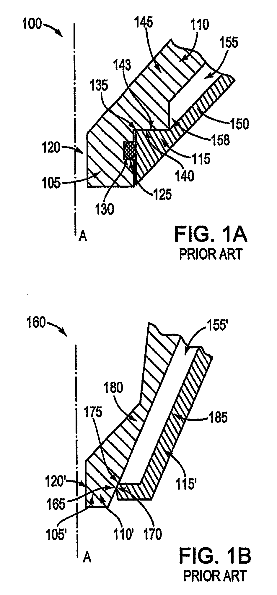
For example, the configuration of the system 100 results in insufficient cooling of the nozzle tip 105.
Moreover, failure of the interface as a seal 175 can result in damage to the torch electrode (not shown) and a shield (not shown), which generally also require replacement.

Method used


Image

  • Plasma arc torch cutting component with optimized water cooling
  • Plasma arc torch cutting component with optimized water cooling
  • Plasma arc torch cutting component with optimized water cooling

Examples


Embodiment Construction

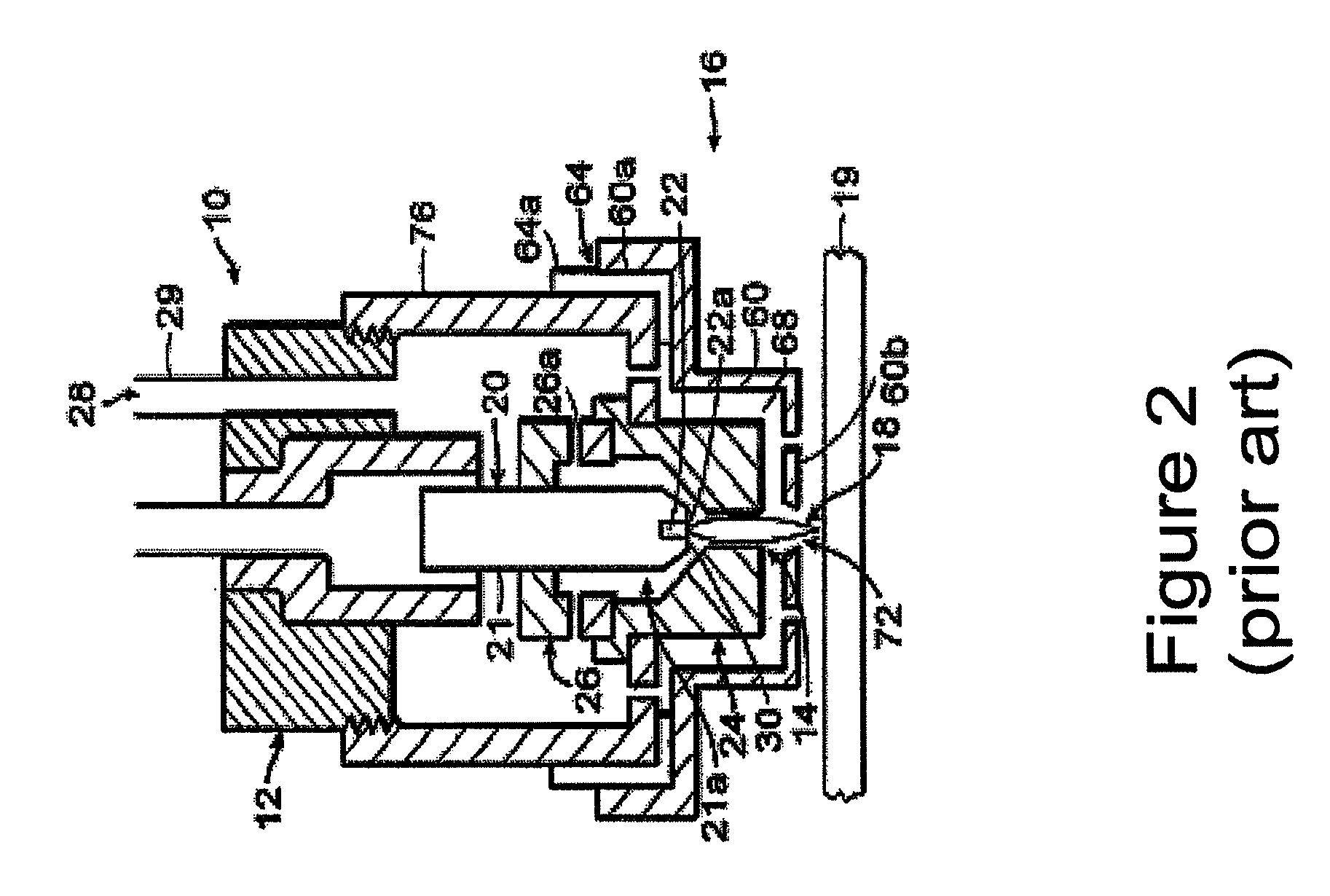
[0071]FIG. 2 illustrates in simplified schematic form of a known plasma arc cutting torch 10 representative of any of a variety of models of torches sold by Hypertherm, Inc., with offices in Hanover, N.H. The torch 10 has a body 12 that is typically cylindrical with an exit orifice 14 at a lower end 16. A plasma arc 18, i.e., an ionized gas jet, passes through the exit orifice 14 and attaches to a workpiece 19 being cut. The torch 10 is designed to pierce and cut metal, particularly mild steel, or other materials in a transferred arc mode. In cutting mild steel, the torch 10 operates with a reactive gas, such as oxygen or air, as the plasma gas 28 to form the transferred plasma arc 18.

[0072]The torch body 12 supports a copper electrode 20 having a generally cylindrical body 21. A hafnium insert 22 can be press fit into the lower end 21a of the electrode 20 so that a planar emission surface 22a is exposed. The torch body 12 also supports a nozzle 24 which is spaced from the electrode...


PUM

PropertyMeasurementUnit
elastomericaaaaaaaaaa
conductiveaaaaaaaaaa
heataaaaaaaaaa

Abstract

A nozzle, retaining cap, or shield for a plasma arc torch that includes a surface defining a conductive contact portion for exchanging heat with an adjacent torch component. The adjacent torch component can be a retaining cap, electrode or nozzle. The surface of the nozzle, retaining cap, or shield can also at least partially define a cooling channel having a curvilinear surface. A sealant portion can be positioned between the conductive contact portion and the cooling channel. The sealant portion can form or create a fluid barrier between the cooling channel and the conductive portion.

Description

CROSS-REFERENCE TO RELATED APPLICATIONS[0001]This application claims the benefit of U.S. Patent Application No. 60 / 900,435, which was filed on Feb. 9, 2007, titled “Plasma Cutting Component With Optimized Water Cooling,” and U.S. patent application Ser. No. 12 / 028,768, which was filed on Feb. 8, 2008, titled “Plasma Arc Torch Cutting Component With Optimized Water Cooling,” the entire contents of both of which are hereby incorporated herein by reference.TECHNICAL FIELD[0002]The invention generally relates to the high-temperature processing of metallic materials, including the cutting of materials using plasma arc cutting torches. More specifically, the invention relates to improved design and cooling techniques that can enhance the performance or life expectancy of plasma torches and components thereof.BACKGROUND[0003]Plasma arc torches are widely used for workpiece processing, e.g., the cutting, piercing, and / or marking of metallic materials (e.g., elemental metals, metal alloys. e...

Claims


Application Information

Patent Timeline
Patent Type & Authority Applications(United States)
IPC IPC(8): B23K9/00
CPCB23K10/00H05H1/34H05H2001/3457H05H2001/3442H05H2001/3436H05H1/3436H05H1/3442H05H1/3457
Inventor YANG, YONGCOOK, DAVID JONATHAN
Owner HYPERTHERM INC
Why Eureka
Try Eureka