Drive device

a technology of drive device and drive shaft, which is applied in the direction of magnetic circuit rotating parts, electric propulsion mounting, magnetic circuit shape/form/construction, etc., can solve the problems of increasing the energy required for driving of electric motors, reducing the temperature of the electric motor housing substantially to such temperature, and avoiding heat conduction

Inactive Publication Date: 2006-09-05
AISIN AW CO LTD
View PDF21 Cites 33 Cited by
  • Summary
  • Abstract
  • Description
  • Claims
  • Application Information

AI Technical Summary

Benefits of technology

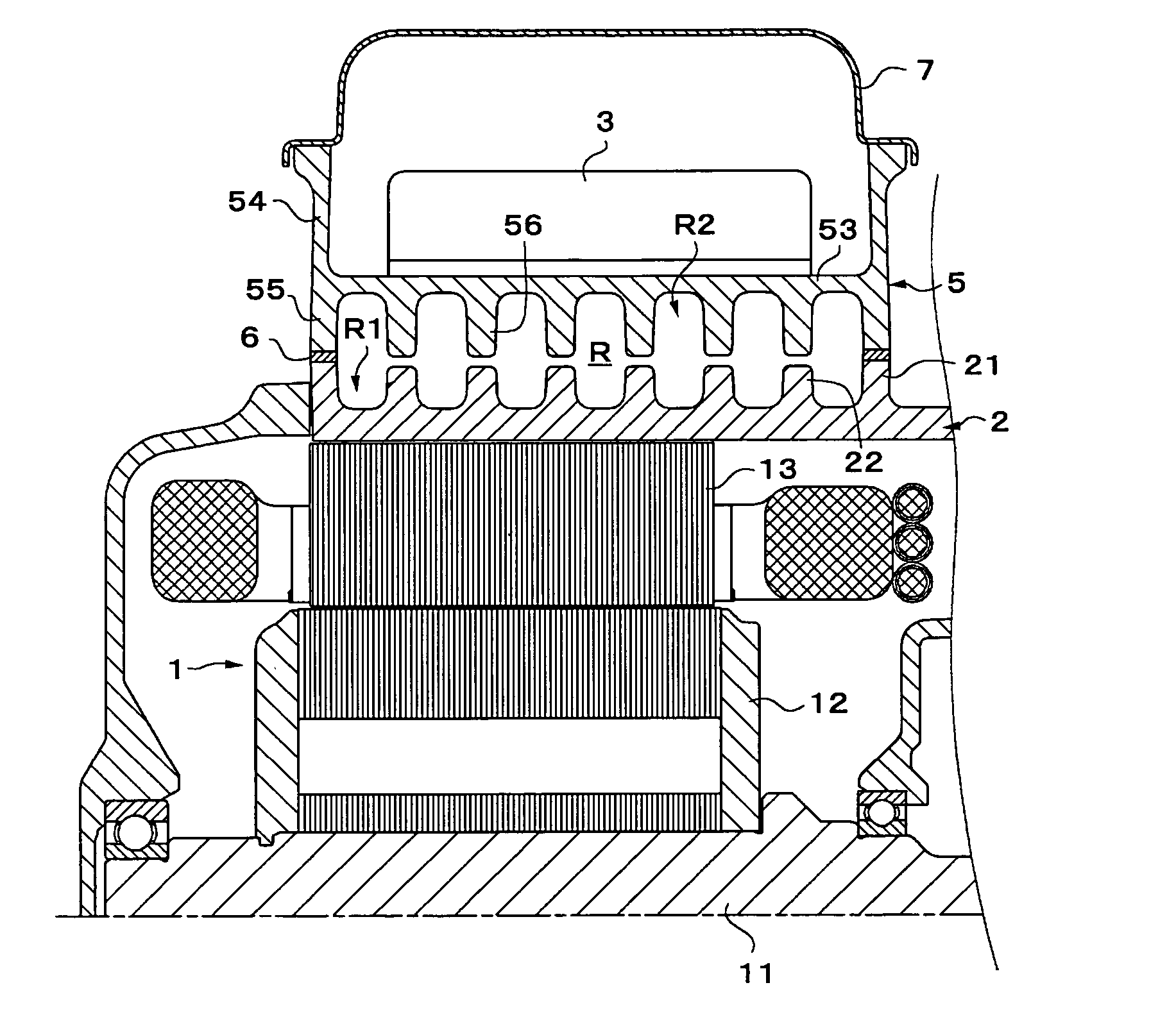
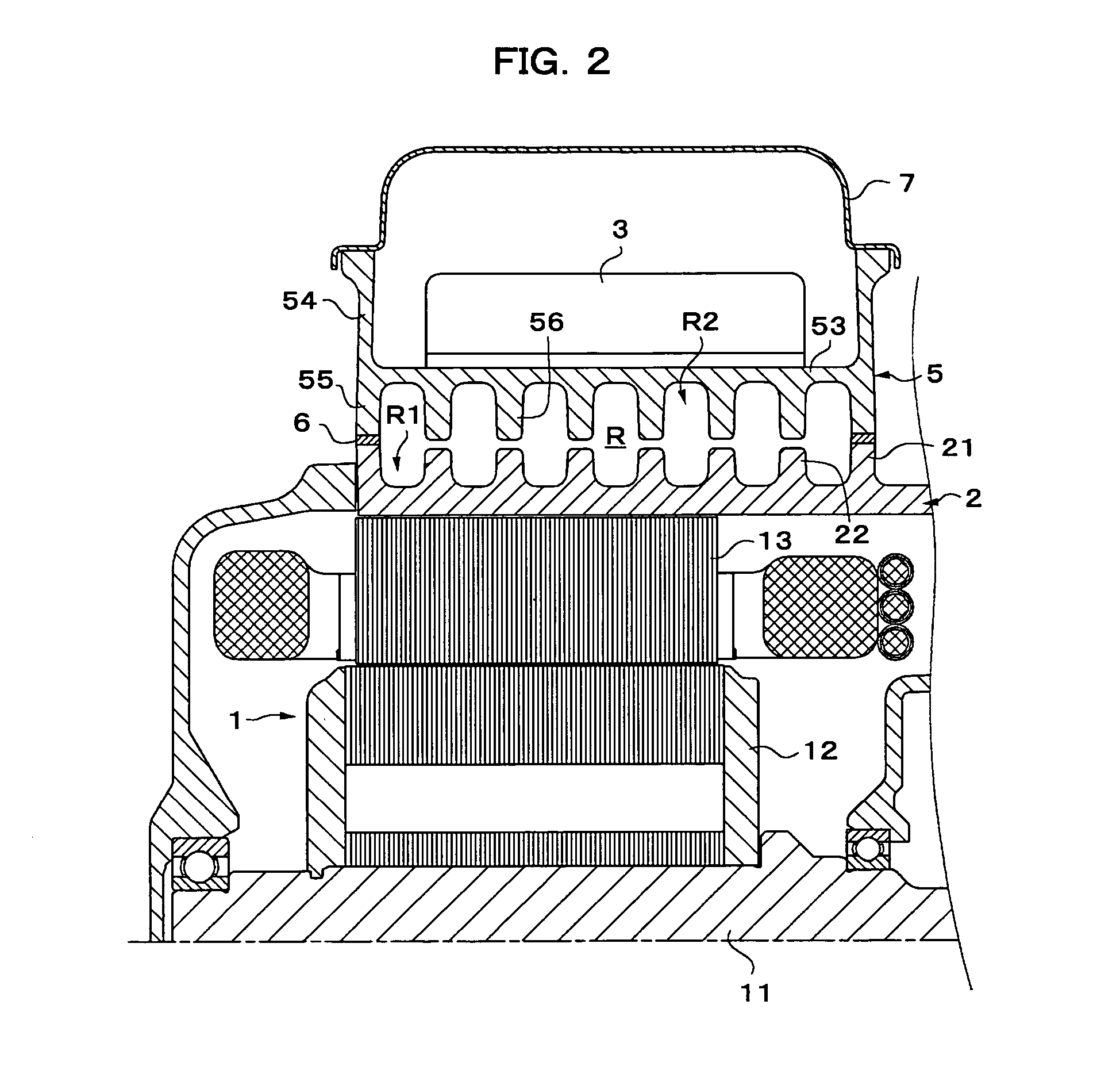
[0010]With the construction, adequate heat conductive areas are ensured on the drive-unit-casing side and the heat-sink side, so that the both sides, respectively, can be effectively cooled by expedited cooling that is caused by heat exchange with a cooling refrigerant in such large areas. Also, since the heat-sink side fins and the drive-unit-casing side fins are apart from each other and so direct heat conduction from the drive unit casing to the heat sink is avoided, it is not required that temperature on the drive-unit-casing side be lowered to the heat-resistant temperature of the control device that is needed on the heat-sink side, and efficient cooling with temperature gradient kept therebetween can be performed. Thereby, a small flow rate of the refrigerant can efficiently prevent temperature rise of the inverter caused by unification of the electric motor and the inverter.
[0011]It is desired in the above construction that the heat-sink side fins and the drive-unit-casing side fins cooperatively generate a common refrigerant flow pattern within the space. Also, with the construction, the fins are used to generate a common refrigerant flow on both the heat-sink side and the drive-unit-casing side within the space, so that it is possible to prevent stagnation due to interference of the refrigerant flow from being generated in the space.
[0013]And, in the case where the both fins comprise the same fins, both the heat-sink side fins and the drive-unit-casing side fins can comprise pin-shaped fins. With such construction, the flow passage resistance can be sharply reduced as compared with the construction, in which the rib-shaped fins guide the fluid flow within the space. Accordingly, this construction makes it possible to reduce pressure loss in the flow passage whereby the inverter united with the drive unit can be cooled with less energy consumption.
[0015]Also, it is desired in the above construction that the heat-sink side fins and the drive-unit-casing side fins cooperatively and substantially cross the space with a minute gap therebetween. With such construction, it is possible to generate a substantially single flow of the cooling fluid free from stagnation due to interference of flow in the space while avoiding heat conduction due to direct contact between the heat-sink side fins and the drive-unit-casing side fins.

Problems solved by technology

Hereupon, with the conventional construction of the former technique, since formation of the cooling flange leads to enlargement of a heat exchange area on a side of the bottom plate that mounts thereto the module, cooling on a side of the module is expedited but cooling on a side of the stator body is not necessarily adequate since a heat exchange area is defined by an area of the groove bottom surface.
On the other hand, with the latter technique, since it is difficult to ensure a sufficient area, in which the sleeve contacts with the cooling fluid, there is a need of increasing the flow rate of a cooling fluid flowing through the spiral path in order to adequately cool inverter components, in which case a pump, etc. for circulation of the cooling fluid becomes large in size and so energy for driving thereof is increased.
Also, with the technique, since a tip end of the wall that defines the spiral path is brought in direct contact with the sleeve, heat conduction is caused at such contact region, so that in order to maintain the inverter components at the heat-resistant temperature thereof or lower, there is a need of cooling that lowers temperature of the housing of the electric motor substantially to such temperature, which is not efficient in terms of cooling efficiency.

Method used


Image

  • Drive device
  • Drive device
  • Drive device

Examples


first embodiment

[0032]Next, FIG. 4 shows a pattern in which the heat-sink side fins 56 and the drive-unit-casing side fins 22 are arranged, in a schematic plan that illustrates a bottom surface of the inverter casing 5 and a mount surface on the side of the drive unit casing 2, the both surfaces being actually in the opposed relationship with each other, in a state, in which the both surfaces are aligned in the same plane. In this embodiment, both the heat-sink side fins 56 and the drive-unit-casing side fins 22 comprise pin-shaped fins that are arranged at equal intervals in the same pattern. In the case of this embodiment, since the both fins coincide with each other in those positions in the space R, in which they are arranged, the heat-sink side fins 56 and the drive-unit-casing side fins 22 are apart from each other with minute gaps therebetween, but they are arranged in the same number so as to cooperatively and substantially cross the space R.

[0033]In the case of the fin arrangement pattern...

third embodiment

[0035]Next, shown in FIG. 6, both heat-sink side fins 56 and drive-unit-casing side fins 22 comprise rib-shaped fins extending from a fluid inlet toward a fluid outlet and arranged in parallel at equal intervals, and the heat-sink side fins 56 and the drive-unit-casing side fins 22 are the same in number so as to cooperatively and substantially cross the space R with minute gaps therebetween. With such arrangement, pressure loss in the entire flow passage is greater than those in the preceding two embodiments, but the cooling efficiency is sharply enhanced since the heat exchanging area is increased.

[0036]Further, according to a fourth embodiment shown in FIG. 7, heat-sink side fins 56 and drive-unit-casing side fins 22 comprise the same rib-shaped fins and the both fins extend from a fluid inlet toward a fluid outlet and are arranged in parallel at equal intervals. In this embodiment, the drive-unit-casing side fins 22 are smaller in number than the heat-sink side fins 56. Like th...

fifth embodiment

[0037]Finally, shown in FIG. 8, heat-sink side fins 56 and drive-unit-casing side fins 22 are configured such that the drive-unit-casing side fins 22 comprise rib-shaped fins while the heat-sink side fins 56 comprise pin-shaped fins. In the case where one of the fins 22, 56 is rib-shaped and the other of them is pin-shaped in this manner, flow in the space on that side, in which the rib-shaped fins are arranged, is disadvantageous in terms of pressure loss but is advantageous in that the flow is forcedly guided in respective regions of the space to be made even. Flow in the space on that side, in which the pin-shaped fins are arranged, is advantageous in that pressure loss is decreased. Accordingly, with such arrangement of the fins, flow resistance in the flow passage within the space can be generally reduced as compared with the case where the fins in the both spaces comprise rib-shaped fins, and the flow characteristic can be made favorable as compared with the case where the fi...


PUM


Abstract

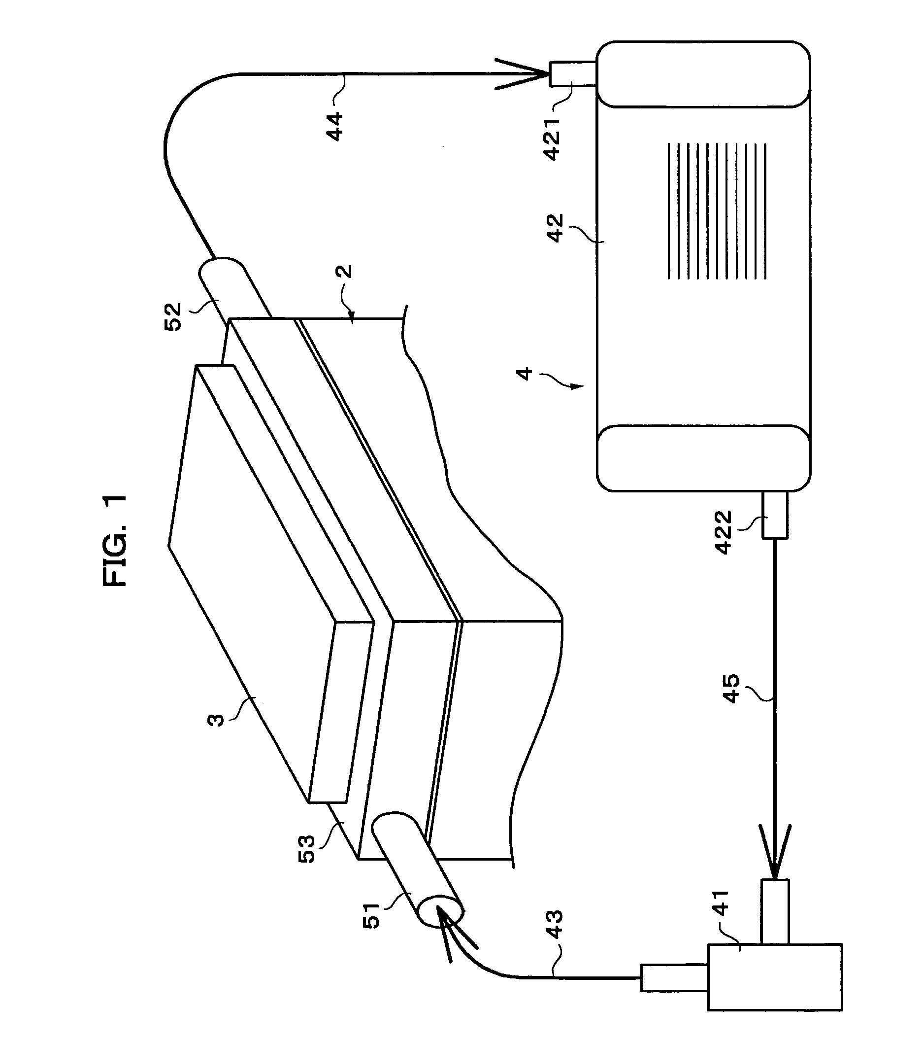
A drive unit comprises an electric motor 1, a drive unit casing 2 accommodating therein the electric motor, an inverter 3 that controls the electric motor, and a flow passage of a refrigerant that cools the inverter. The inverter is mounted on a heat sink 53 and mounted to the drive unit casing with a space R defined, and the space is communicated to the flow passage of the refrigerant. The heat sink comprises fins 56, and the drive unit casing comprises fins 22, the both fins being apart from each other. Thereby, both a side of the drive unit casing and a side of the heat sink are effectively cooled by heat exchange with a cooling refrigerant in wide areas. Also, the fins are apart from each other whereby direct heat conduction is avoided and efficient cooling is enabled with temperature gradient conformed to heat-resistant temperatures.

Description

TECHNICAL FIELD[0001]The present invention relates to a drive unit that uses an electric motor as a power source, and, more particular, to a cooling technique in drive units for electric cars and drive units for hybrid cars.BACKGROUND ART[0002]In the case where an electric motor is used as a power source for vehicles, the electric motor needs a control device (an inverter in the case of an AC electric motor) for control thereof. Since the control device such as inverters, etc. is connected to the electric motor by way of power cable, it can be arranged in an appropriate position apart from the electric motor. For the convenience for a car-mounted arrangement, there is in some cases adopted an arrangement, in which the control device is united with the electric motor.[0003]By the way, control devices in current technology are lower in heat-resistant temperature than electric motors. Hereupon, in the case where a control device is to unite with an electric motor in the above-mentioned...

Claims


Application Information

Patent Timeline
Patent Type & Authority Patents(United States)
IPC IPC(8): H02K1/32B60K6/26B60L50/16H02K5/20H02K7/00H02K9/19H02K11/04H05K7/14H05K7/20
CPCH02K5/20H05K7/20927H02K9/19H02K11/0073H02K7/006B60K6/26B60K2001/003H02K11/33H02K5/203B60K11/02B60Y2200/91B60Y2200/92H02K5/18
Inventor TAKENAKA, MASAYUKIKUTSUNA, NARUHIKOYAMAGUCHI, KOZO
Owner AISIN AW CO LTD
Why Eureka
Try Eureka