Main shaft apparatus

A spindle device and bearing technology, which is applied in the direction of large fixed members, metal processing machinery parts, maintenance and safety accessories, etc., can solve problems such as heat sticking, wear, and preload increase

Active Publication Date: 2013-03-27
NSK LTD
View PDF25 Cites 25 Cited by
  • Summary
  • Abstract
  • Description
  • Claims
  • Application Information

AI Technical Summary

Problems solved by technology

As a result, the sliding of the bearing sleeve is hindered, resulting in poor sliding, a pushing force is generated between the fixed end bearing and the floating end bearing, and the surface pressure of the rolling contact part of the bearing increases, resulting in an increase in preload or thermal adhesion.
[0011] In addition, when thermal expansion is considered and the gap is set initially to be large to prevent sliding failure, vibration may occur between the bearing sleeve and the housing during low-speed operation (low heat generation), or the vibration may be the cause. Fretting wear occurs, causing problems such as wear or adhesion of the part
As a result, wear debris intrudes into the bearing, causing damage to the bearing, or causing poor sliding due to adhesion, resulting in adverse effects

Method used


Image

  • Main shaft apparatus
  • Main shaft apparatus
  • Main shaft apparatus

Examples


no. 1 approach )

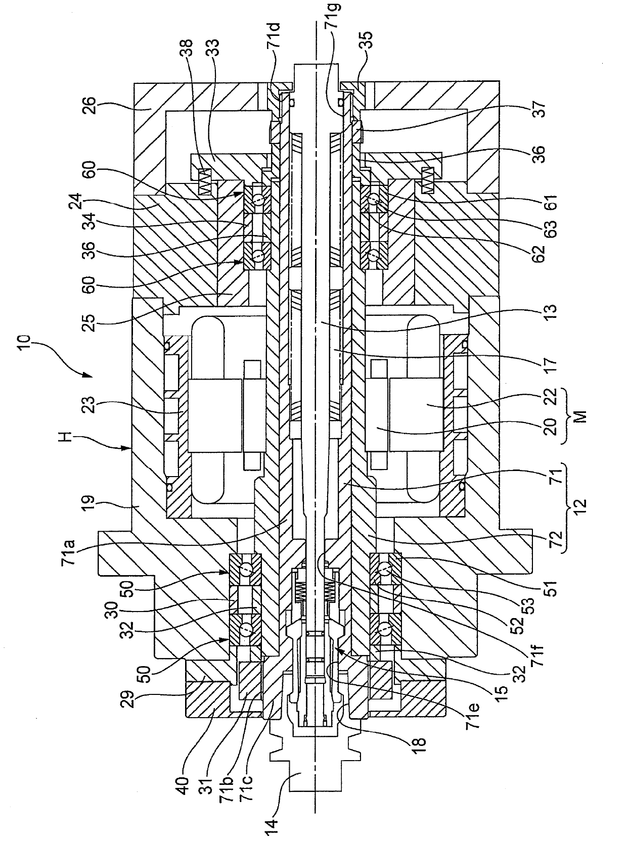
[0193] like figure 1 As shown, the spindle device 10 has a built-in motor, and a hollow rotating shaft 12 is provided at the axial center thereof, and a slidable drawbar 13 is inserted into the shaft core of the rotating shaft 12 . The pull rod 13 exerts force on the collet portion 15 of the fixed tool holder 14 in the direction opposite to the tool (right direction in the figure) by the force of the disc spring 17, and the tool holder 14 fits into the conical surface 18 of the rotating shaft 12. . A tool (not shown) is attached to the tool holder 14 , and as a result, the tool can be attached to one end (left side in the figure) of the rotary shaft 12 so as to sandwich the tool.

[0194] In addition, the rotating shaft 12 is supported on the housing H by the two rows of front bearings 50, 50 supporting the tool side of the rotating shaft 12 and the two rows of rear bearings 60, 60 supporting the opposite side of the tool, so that it can be Free spins. It should be noted t...

no. 2 approach )

[0235] Next, refer to Figure 4 A spindle device according to a second embodiment of the present invention will be described in detail. In addition, the same code|symbol is attached|subjected to the same or equivalent part as 1st Embodiment, and the description is abbreviate|omitted or simplified.

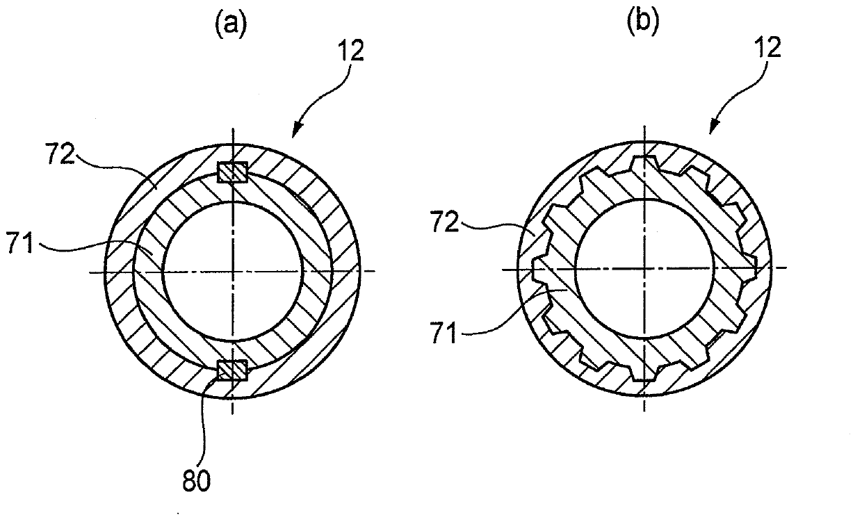
[0236] In the second embodiment, in addition to the first cylindrical member 71 made of a metal material and the second cylindrical member 72 made of a carbon fiber composite material (CFRP) as in the first embodiment, the rotating shaft 12 also has Arranged on the outer peripheral surface of the second sleeve member 72, the inner rings 52, 52 of the front bearings 50, 50 and the inner rings 62, 62 of the rear bearings 60, 60 are respectively fitted on the outer peripheral surfaces. Two third cylindrical members 73,74.

[0237] The second cylindrical member 72 has stepped portions 72a, 72b at the front and rear portions of the outer peripheral surface away from the axially interm...

no. 3 approach )

[0261] Next, refer to Figure 7 , the spindle device according to the third embodiment of the present invention will be described in detail. In addition, the same code|symbol is attached|subjected to the same or equivalent part as 1st Embodiment, and the description is abbreviate|omitted or simplified.

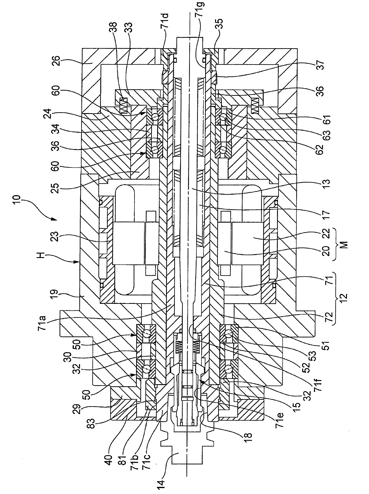
[0262] In the third embodiment, the rotor 20 of the motor M is configured to be rotatable integrally with the rotary shaft 12 via the rotor sleeve 70 . In addition, the rotary shaft 12 is made of a metal material, and on the other hand, the rotor sleeve 70 is made of a carbon fiber composite material (CFRP). Carbon fiber composite materials (CFRP) use materials with lower heat transfer coefficient and thermal expansion coefficient than metal materials, higher specific elastic modulus and lower specific gravity than metal materials. In particular, by making the rotor sleeve 70 made of carbon fiber composite material with a small heat transfer coefficient and disposing it betw...


PUM


Abstract

A main shaft apparatus (10) of a built-in motor system, wherein a rotary shaft (12) is provided with: a first cylindrical component (71) made of metal material; and a second cylindrical component (72) made of carbon fibre composite material, which is positioned on the outer peripheral surface of the first cylindrical component (71) and into the outer peripheral surface of which a rotor (20) fits. By virtue of this, the temperature increase of the rotary shaft and a bearing due to the heat produced by the rotor can be controlled and processing precision can be improved.

Description

technical field [0001] The present invention relates to a spindle device, in particular to a spindle box suitable for a double-column machining center, a multi-coordinate control machine tool, etc., and a spindle device capable of high-speed rotation with a dmn of more than 1 million. Background technique [0002] Since the rotating shaft of a spindle device applied to a machine tool needs to be subjected to a machining load while rotating at a high speed, it is necessary to maintain rigidity against the machining load, or maintain deformation suppression characteristics against the centrifugal force during high-speed rotation, etc., as its The material is mainly metal. In addition, the rotary shaft is used by changing tools (knives), and therefore, it is also required to have wear resistance and hardness. Therefore, due to the physical properties of the metal, there are limits to its characteristic value and thermal expansion, and the rotation speed and acceleration / decele...

Claims


Application Information

Patent Timeline
Patent Type & Authority Applications(China)
IPC IPC(8): B23B19/02
CPCB23Q1/70B23Q11/127
Inventor 米山博树岩崎修小栗翔一郎稻垣好史胜野美昭
Owner NSK LTD
Why Eureka
Try Eureka