Magnetically attached lighted sign

a technology of magnetic attachment and lighted signs, which is applied in the direction of mobile visual advertising, instruments, lighting support devices, etc., can solve the problems of not providing efficient electrical grounding using the vehicle surface, existing devices are not adapted for use with non-conventional vehicles, etc., and achieves efficient circuit operation and simplified construction

Inactive Publication Date: 2005-06-16
SCHNEIDER TODD T
View PDF16 Cites 14 Cited by
  • Summary
  • Abstract
  • Description
  • Claims
  • Application Information

AI Technical Summary

Benefits of technology

[0004] A lighted sign for magnetic application to a vehicle surface according to the present invention includes first and second metallic layers with a magnetic plate sandwiched therebetween. The metallic layers may have a foil construction. The second metallic layer includes a circumference smaller than that of the magnetic plate such that it is pressed tightly against a vehicle surface when the magnetic plate is magnetically applied and adhered thereto. A light source, such as a plurality of light emitting diodes, is coupled to the magnetic plate and includes positive wires electrically connected to the first metallic layer and negative wires electrically connected to the second metallic layer. Therefore, a circuit is formed such that the light source may be energized to emit light when the first metallic layer is connected to a vehicle power source. And, the light source is properly grounded when the second metallic layer is pressed against a metal surface of the vehicle. Utilizing the vehicle surface as the grounding layer simplifies construction and allows efficient circuit operation.

Problems solved by technology

Although assumably effective for their intended purposes, the existing devices are not adapted for use with non-conventional vehicles, such as horse trailers and the like, and do not provide efficient electrical grounding using the vehicle surface to which the sign is applied.

Method used


Image

  • Magnetically attached lighted sign
  • Magnetically attached lighted sign
  • Magnetically attached lighted sign

Examples


Embodiment Construction

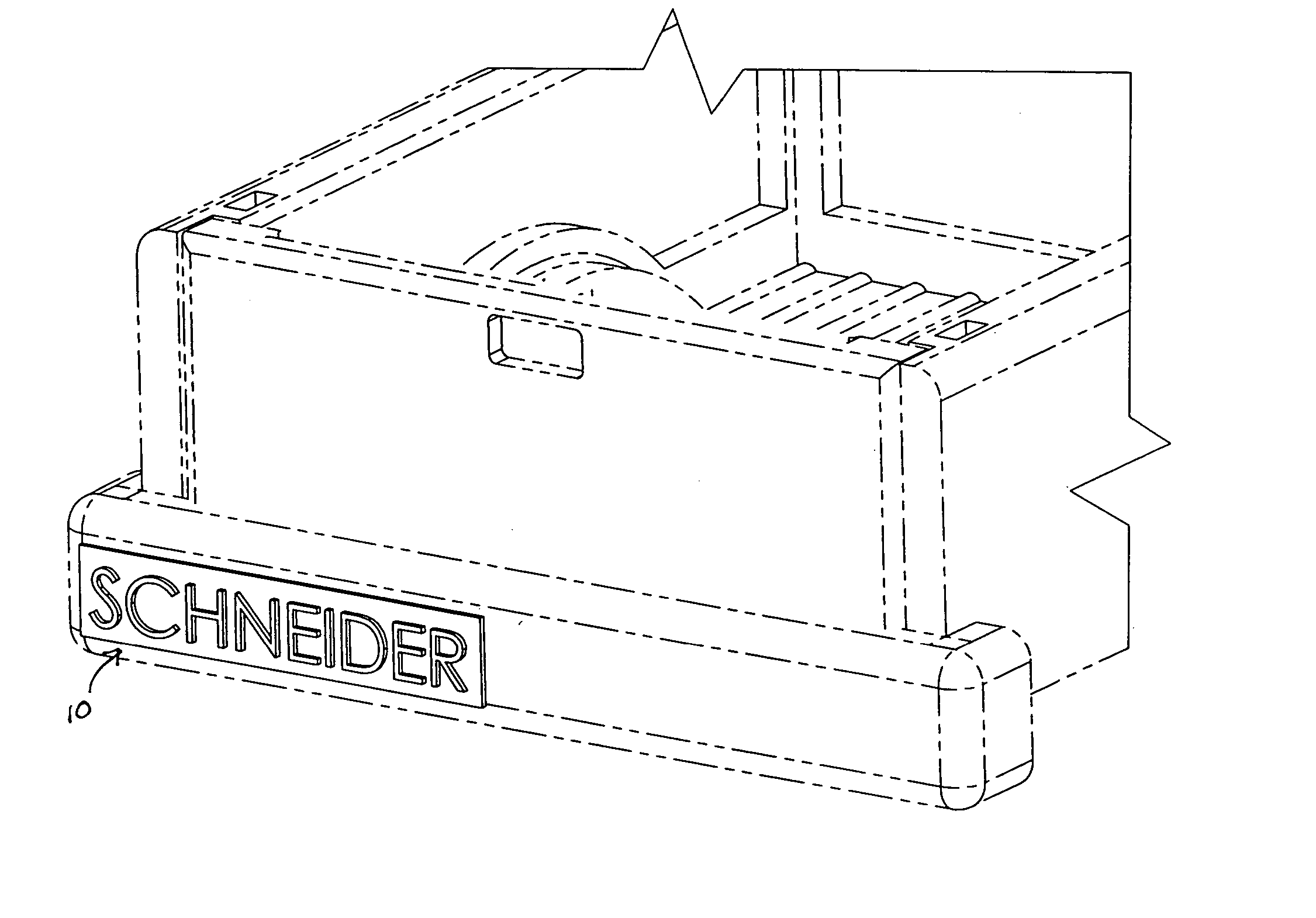
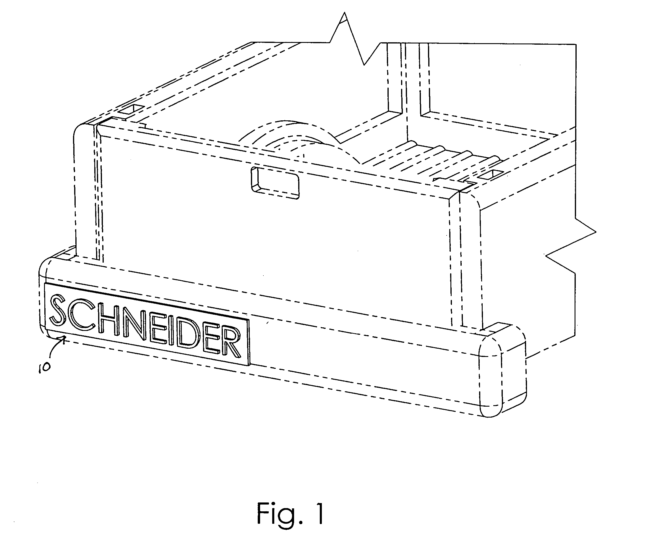
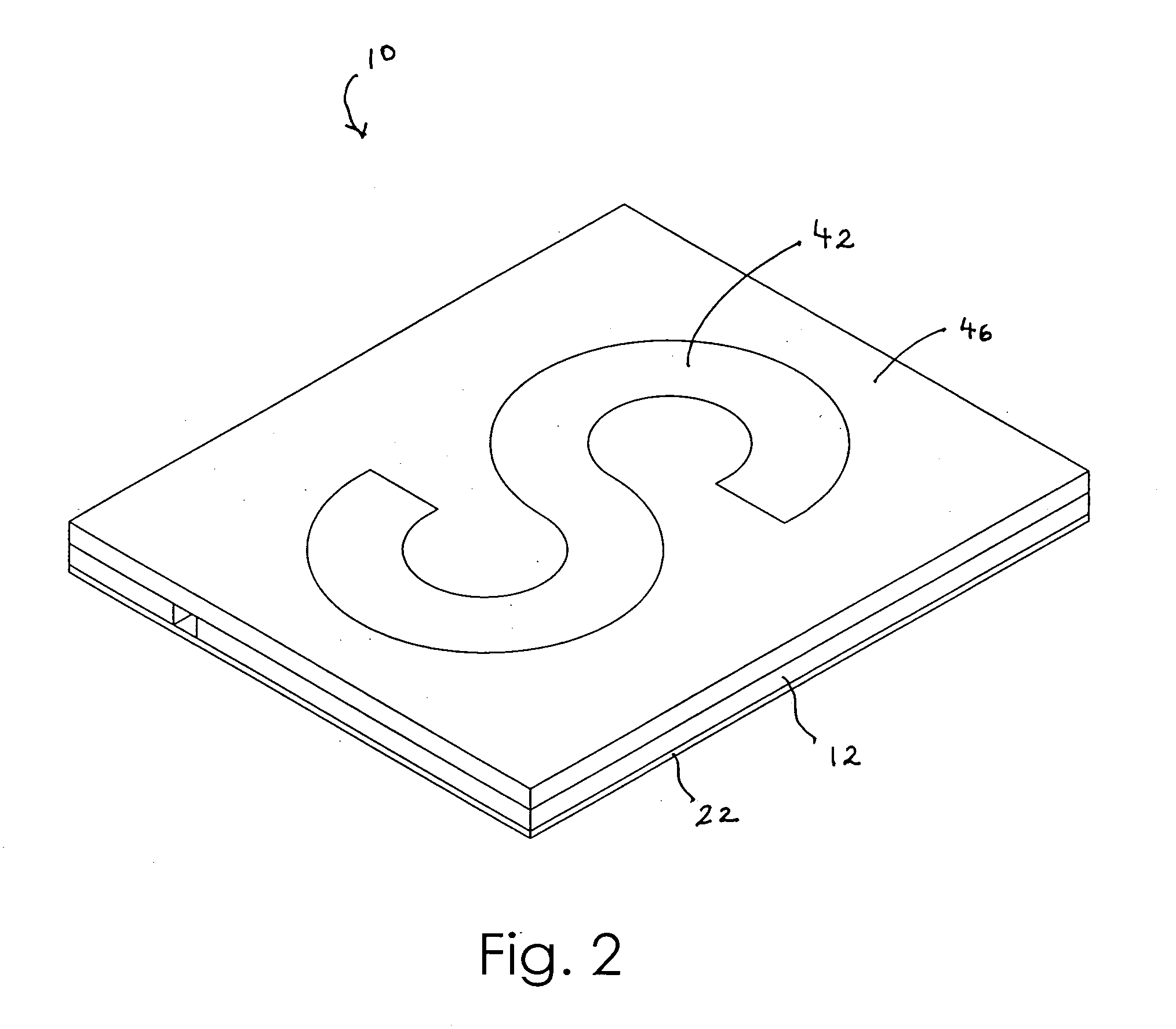
[0018] A lighted sign for magnetic attachment to a vehicle surface according to the present invention will now be described in detail with reference to FIGS. 1 through 6 of the accompanying drawings.

[0019] Now more particularly, a lighted sign 10 according to one embodiment of the present invention includes a first metallic layer 12 and a second metallic layer 20 with a magnetic plate 22 sandwiched therebetween. It should be observed and appreciated that the multiple layers of the lighted sign 10 are pressed together in a pressure, friction, adhesive, or other suitable attachment. As shown in FIG. 3, the second metallic layer 20 is immediately adjacent a rear surface of the magnetic plate 22 whereas the first metallic layer 12 is positioned adjacent a front surface of the magnetic plate 22. At least the rear surface of the magnetic plate 22 is capable of being magnetically adhered to a metallic vehicle surface, such as a bumper, door, tailgate, or the like. As the circumference and...


PUM


Abstract

A lighted sign for application to a vehicle surface includes first and second metallic layers with a magnetic plate sandwiched therebetween. The second metallic layer includes a circumference smaller than that of the magnetic plate such that it is pressed against a vehicle surface when the magnetic plate is magnetically adhered thereto. A light source is coupled to the magnetic plate with a positive wire connected to the first metallic layer and a negative wire connected to the second layer such that the light source emits light when the first metallic layer is energized by a vehicle electrical power source and is grounded when the second metallic layer is pressed against the vehicle metallic surface. The magnetic plate and first metallic surface include cutouts so that light may be emitted by the light source therethrough. The lighted sign 10 include a microcontroller and environmental sensors for advanced lighting control.

Description

BACKGROUND OF THE INVENTION [0001] This invention relates generally to lighted signs and, more particularly, to a lighted sign that may be magnetically attached to a vehicle surface and which utilizes the vehicle for both electrical power and grounding. [0002] Lighted signs for use in advertising, decorative lighting, and even automobile accessories are generally known. Although assumably effective for their intended purposes, the existing devices are not adapted for use with non-conventional vehicles, such as horse trailers and the like, and do not provide efficient electrical grounding using the vehicle surface to which the sign is applied. [0003] Therefore, it is desirable to have a lighted sign that may be removably and magnetically attached to a vehicle surface such as an automobile or trailer. Further, it is desirable to have a lighted sign that may be energized by a vehicle electrical power source and efficiently grounded by the vehicle itself when the sign is attached theret...

Claims


Application Information

Patent Timeline
Patent Type & Authority Applications(United States)
IPC IPC(8): B60Q1/26B60Q1/50G09F7/04G09F21/04
CPCB60Q1/2615B60Q1/50Y10S362/812G09F21/04G09F7/04B60Q1/503B60Q1/543
Inventor SCHNEIDER, TODD T.
Owner SCHNEIDER TODD T
Why Eureka
Try Eureka