Fusing roller apparatus of electro-photographic image forming apparatus, and a process of manufactuing a fusing roller apparatus

a technology of electro-photographic image and fusing roller, which is applied in the direction of electrographic process apparatus, instruments, optics, etc., can solve the problems of slow heat transfer speed, unnecessarily large power consumption of conventional fusing roller apparatus using halogen lamps as heat sources, and insufficient heat exchange speed of conventional fusing roller apparatus, etc., to achieve good insulation characteristics, small current and power consumption, and increase the temperature of fusing roller

Inactive Publication Date: 2005-06-16
SAMSUNG ELECTRONICS CO LTD
View PDF6 Cites 17 Cited by
  • Summary
  • Abstract
  • Description
  • Claims
  • Application Information

AI Technical Summary

Benefits of technology

[0014] The present invention provides a fusing roller apparatus of an electro-photographic image forming apparatus which consumes a small amount of current and power, increases a temperature of a fusing roller to a target fusing temperature within a short period of time, and has a good insulation characteristic.

Problems solved by technology

A conventional fusing roller apparatus using a halogen lamp as a heat source unnecessarily consumes a large amount of power.
In particular, the conventional fusing roller apparatus requires considerably long warm-up time until it reaches a target fusing temperature after power is turned on for a printing operation.
In the conventional fusing roller apparatus, a fusing roller is heated by radiant heat from the heat source, which results in a slow heat transfer speed.
In particular, compensation for temperature variations due to a drop in the temperature of the fusing roller caused by contact with printing paper is delayed, so that it is difficult to uniformly control the distribution of temperature along the axial length of the fusing roller.
Also, even in the standby mode where the operation of the printer is suspended, power must be periodically applied to the heat source to keep the temperature of the fusing roller constant, thereby causing unnecessary power consumption.
Moreover, it takes a considerable amount of time to switch the fusing roller from its standby mode to an operation mode for image output, so that the resultant image cannot be rapidly printed.

Method used


Image

  • Fusing roller apparatus of electro-photographic image forming apparatus, and a process of manufactuing a fusing roller apparatus
  • Fusing roller apparatus of electro-photographic image forming apparatus, and a process of manufactuing a fusing roller apparatus
  • Fusing roller apparatus of electro-photographic image forming apparatus, and a process of manufactuing a fusing roller apparatus

Examples


Embodiment Construction

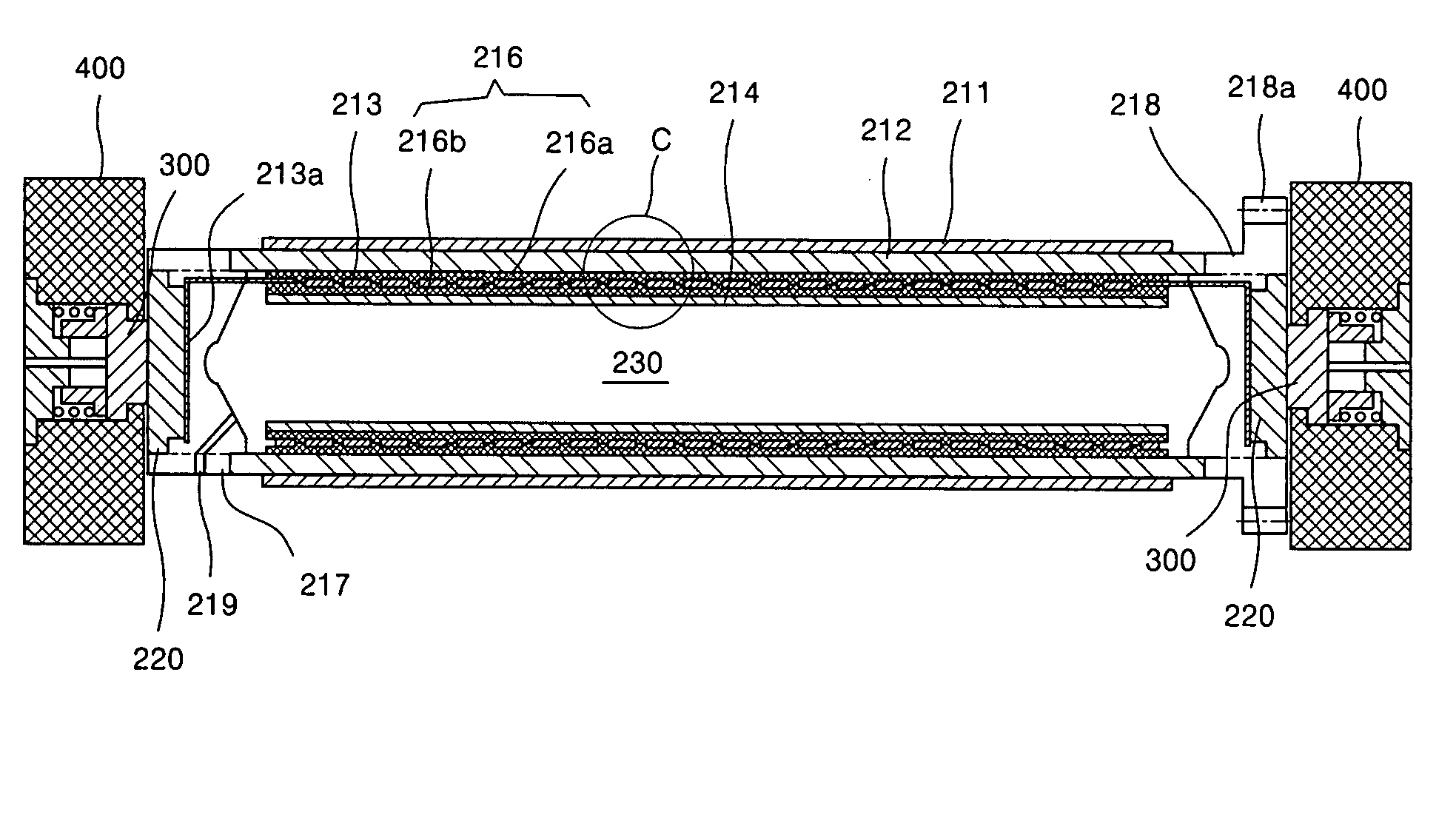
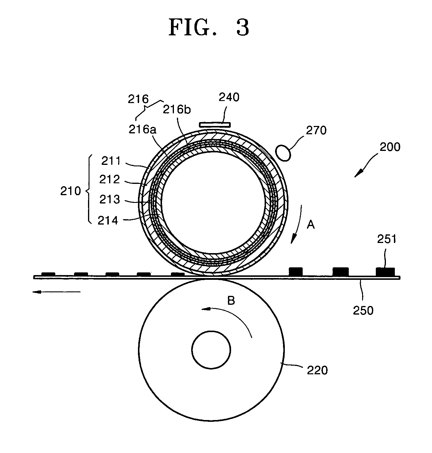
[0023] Referring to FIGS. 3 and 4, a fusing roller apparatus 200 of an electro-photographic image forming apparatus, according to an embodiment of the present invention, applies heat and pressure to a toner image 251 to fuse and fix the toner image 251 to printing paper 250. The fusing roller apparatus 200 includes a fusing roller 210 which is installed to rotate in a direction indicated by arrow “A” so as to apply heat to the toner image 251 and a pressure roller 220 which faces the fusing roller 210 to press the toner image 251 against the fusing roller 210. Here, the printing paper 250 is transferred between the fusing roller 210 and the pressure roller 220.

[0024] The fusing roller 210 includes a cylindrical fusing unit 212, an internal pipe 214, a heat generator 213, and an insulating layer 216. A protection layer 211, which is coated with Teflon, is formed on the surface of the fusing unit 212. The internal pipe 214 is installed inside the fusing unit 212 and has two ends that...


PUM


Abstract

A fusing roller apparatus, and a process of manufacturing thereof, of an electro-photographic image forming apparatus including a cylindrical internal pipe, a fusing unit which is installed to enclose the internal pipe, a heat generator which is installed between the fusing unit and the internal pipe to generate heat, and an insulating layer which includes a first insulating layer that is formed between the heat generator and the fusing unit and a second insulating layer that is formed between the heat generator and the internal pipe to be thicker than the first insulating layer.

Description

BACKGROUND OF THE INVENTION [0001] This application claims the benefit under 35 U.S.C. §119(a) of Korean Patent Application No. 2003-91176, filed on Dec. 15, 2003, in the Korean Intellectual Property Office, the entire disclosure of which is incorporated herein by reference. [0002] 1. Field of the Invention [0003] The present invention relates to an electro-photographic image forming apparatus, and more particularly, the present invention relates to a fusing roller apparatus, and a process of manufacturing thereof, of an electro-photographic image forming apparatus for applying heat and pressure to a toner image to fuse and fix the toner image to printing paper. [0004] 2. Description of the Related Art [0005] In general, electro-photographic image forming apparatuses include a fusing roller apparatus that applies heat and pressure to a toner image transferred to a printing medium so as to fuse and fix the toner image to the printing medium. [0006]FIG. 1 is a lateral schematic cross-...

Claims


Application Information

Patent Timeline
Patent Type & Authority Applications(United States)
IPC IPC(8): G03G15/20
CPCG03G15/2053G03G2215/2048
Inventor KIM, HWAN-GUEM
Owner SAMSUNG ELECTRONICS CO LTD
Why Eureka
Try Eureka