Eureka AIR delivers breakthrough ideas for toughest innovation challenges, trusted by R&D personnel around the world.

Receiving apparatus, and display apparatus and television broadcasting system therewith

Active Publication Date: 2007-02-22
PANASONIC CORP
View PDF6 Cites 80 Cited by
  • Summary
  • Abstract
  • Description
  • Claims
  • Application Information

AI Technical Summary

Benefits of technology

[0005] It is an object of the present invention to provide a receiving apparatus which is capable of reducing a power consumption sufficiently by switching a power-supply state at any time, and a display apparatus and a television broadcasting system with the identical apparatus.
[0006] It is another object of the present invention to provide a receiving apparatus which is capable of reducing a power consumption enough in a sleep mode, and receiving a start signal for switching from the sleep mode to a power-on mode at an optional time, and a display apparatus and a television broadcasting system in which the same apparatus is used.

Problems solved by technology

However, in this terminal, the CPU needs to turn on and off the switch circuit.
Hence, in the terminal equipment, a power consumption cannot be reduced enough at the time of the sleep mode.
Thus, such downstream data for turning on or off the switch circuit cannot be transmitted at an arbitrary time.

Method used


Image

  • Receiving apparatus, and display apparatus and television broadcasting system therewith
  • Receiving apparatus, and display apparatus and television broadcasting system therewith
  • Receiving apparatus, and display apparatus and television broadcasting system therewith

Examples


Embodiment Construction

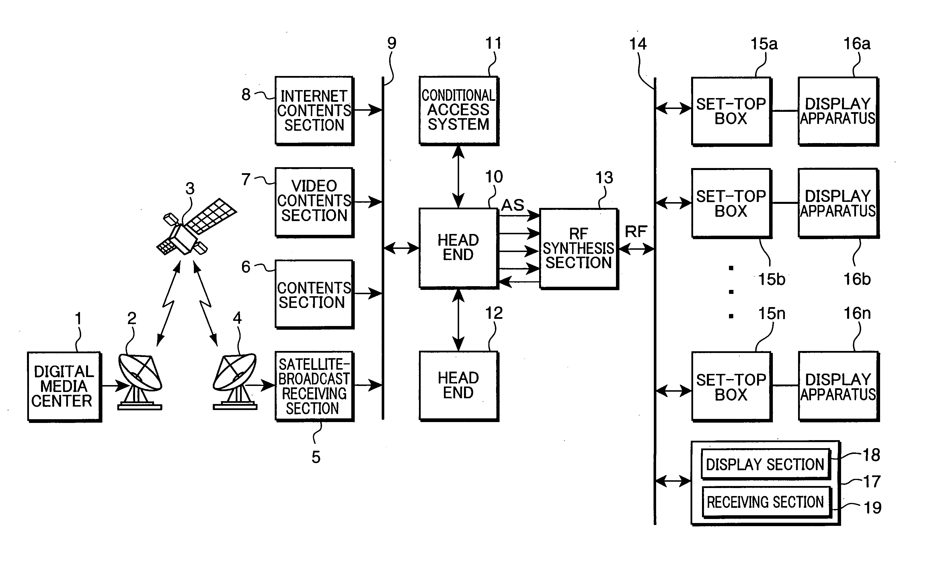
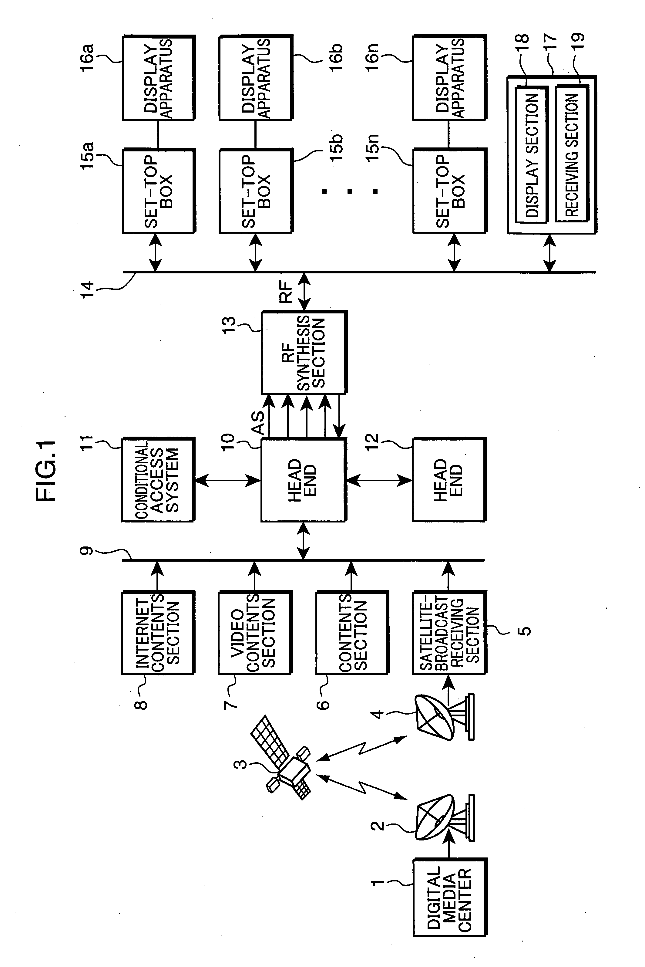
[0049] Hereinafter, a head end which is used for a CATV system as a receiving apparatus according to an embodiment of the present invention will be described with reference to the drawings. FIG. 1 is a block diagram, showing a configuration of the CATV system which is configured by using the head end according to the embodiment of the present invention.

[0050] The CATV system shown in FIG. 1 includes: a digital media center 1; a radio-wave transmitter 2; a broadcasting satellite 3; a radio-wave receiver 4; a satellite-broadcast receiving section 5; a contents section 6; a video contents section 7; an Internet contents section 8; a LAN (or local area network) 9; a head end 10; a conditional access system 11; another head end 12; an RF synthesis section 13; a cable network 14; set-top boxes 15a to 15n; display apparatus 16a to 16n; and a unit display apparatus 17.

[0051] Using the radio-wave transmitter 2, the digital media center 1 transmits various digital broadcast waves or the lik...


PUM


Abstract

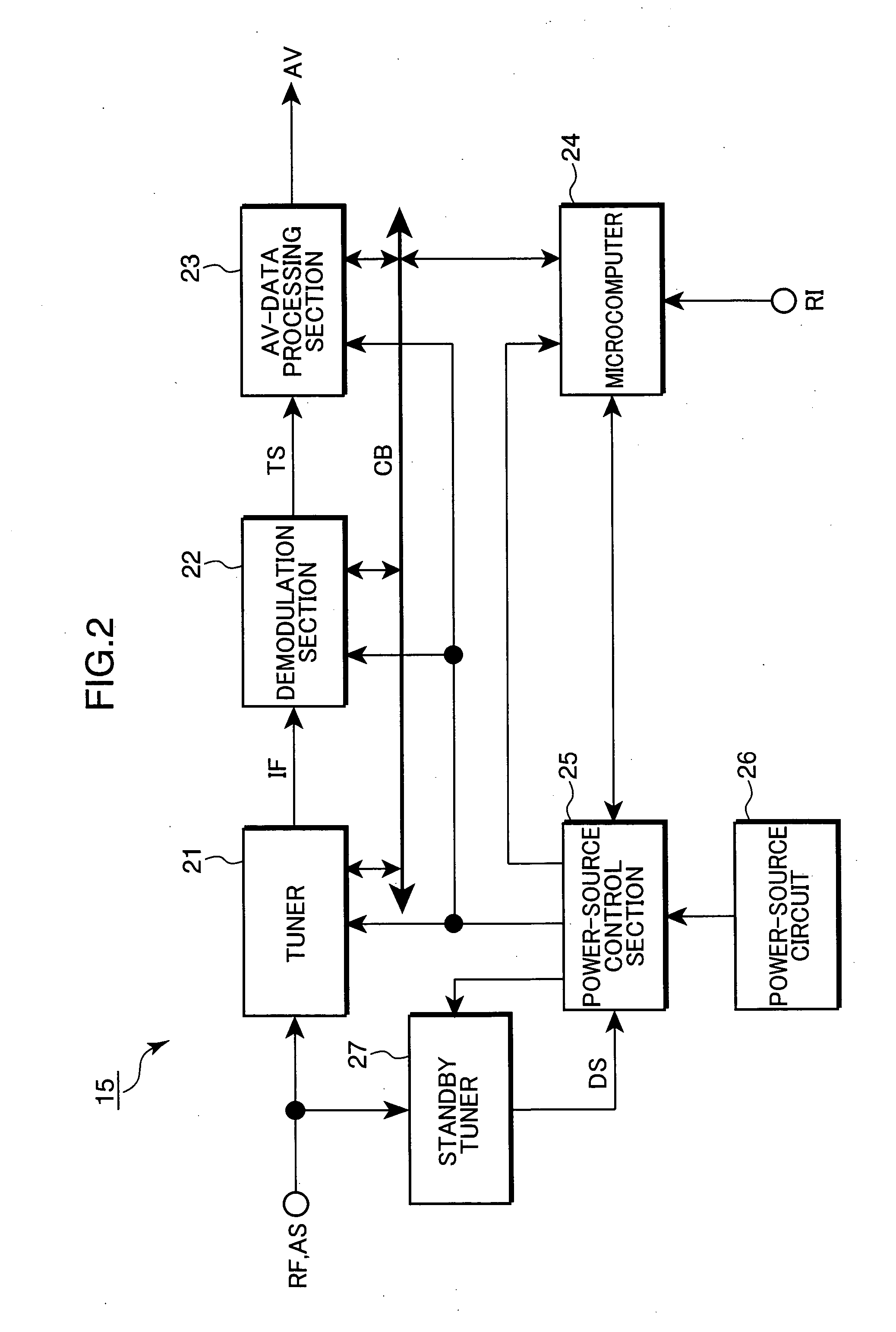
At the time of a sleep mode, a power-source control section stops the power supply to a tuner, a demodulation section, an AV-data processing section and a microcomputer, and executes a power supply only to a standby tuner. The standby tuner receives a start signal which is transmitted from a head end, using a frequency except a specific frequency which is received by the tuner, and outputs a power-supply instruction signal according to the start signal. The power-source control section executes a power supply to the tuner, the demodulation section, the AV-data processing section and the microcomputer, in response to the power-supply instruction signal.

Description

TECHNICAL FIELD [0001] The present invention relates to a receiving apparatus which receives a broadcast signal from a broadcasting-station apparatus, and a display apparatus and a television broadcasting system in which this receiving apparatus is used. It relates to, for example, a receiving apparatus which receives a broadcast signal from a head-end apparatus of a CATV (or cable television) station, and a display apparatus and a CATV system in which this receiving apparatus is used. BACKGROUND ART [0002] In the United States, a CATV system has become popular which can broadcast through a large number of channels. Besides, a digital broadcasting method has enabled high-definition broadcasting using a lot of channels. As such a CATV system, for example, Japanese Patent Laid-Open No. 2002-308030 specification discloses the following CATV system. In order to realize the saving of power in terminal equipment as the receiving apparatus, there are provided a head end which transmits dow...

Claims


Application Information

Patent Timeline
IPC IPC(8): H04N7/173H04N5/44H04B1/16H04H20/00H04H20/34H04H60/09H04N5/50H04N5/63H04N7/16
CPCH04N5/50H04N5/63H04N7/165H04N21/4263H04N21/4432H04N21/6543
Inventor KOGA, FUMIAKI
Owner PANASONIC CORP
Why Eureka
Eureka Blog
Learn More