Structure of connector

Inactive Publication Date: 2005-06-16
YEH SHENG HSING
View PDF4 Cites 139 Cited by
  • Summary
  • Abstract
  • Description
  • Claims
  • Application Information

AI Technical Summary

Benefits of technology

[0008] Thus, a primary objective of the present invention is to provide a structure of socket connector that provides a large contact area with a pin of a plug connector and has a low insertion force to realize firm engagement between the plug connector and the socket connector.
[0009] To achieve the above objective, in accordance with one aspect of the present invention, a connector comprises a housing having a rear face forming at least one receptacle and upper and lower faces each forming a slot, a hole being defined in each slot and extending through the upper and lower faces into the receptacle, a securing hole being defined in the upper face and in communication with the receptacle; a terminal received in each receptacle of the housing, the

Problems solved by technology

Although engagement can be effectively formed between the inserted pin and the conductor protection element of the terminal block, since the protection element has a triangular configuration with an opening and since the pin has a post-like configuration, when the pin is inserted into the conductor protection element, the conductor protection element hardly completely surrounds the pin, forming a ga

Method used


Image

  • Structure of connector
  • Structure of connector
  • Structure of connector

Examples


Embodiment Construction

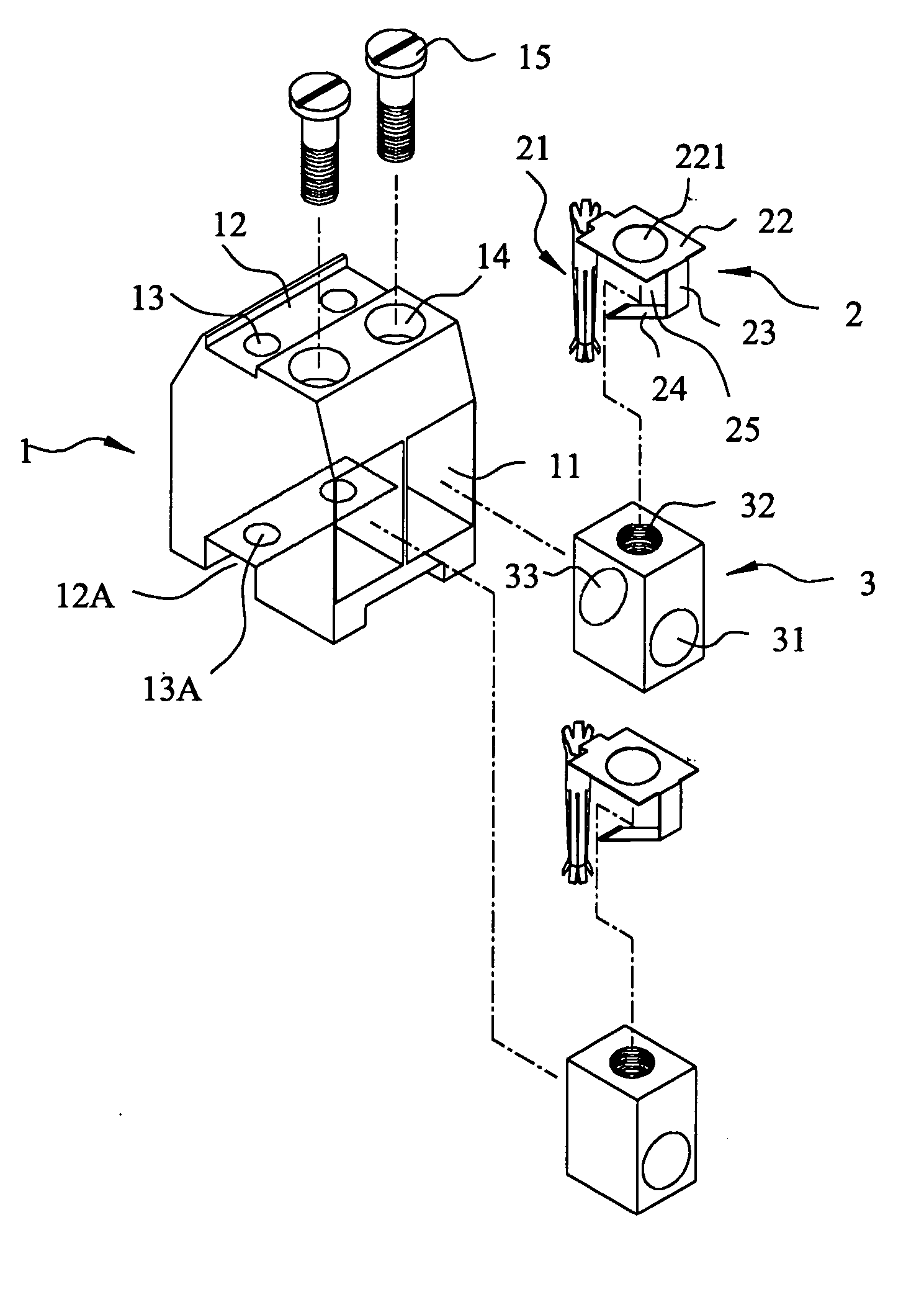
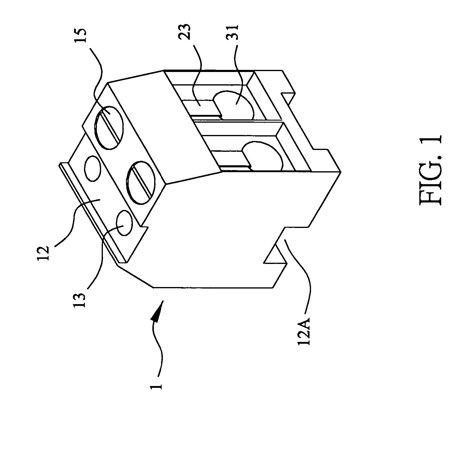
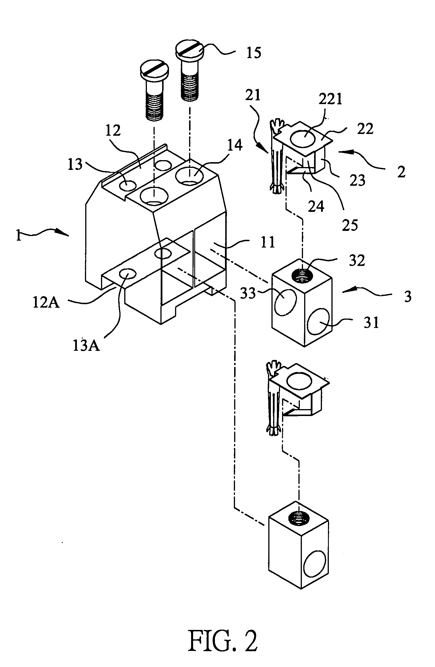
[0017] With reference to the drawings and in particular to FIGS. 1-3, a socket connector constructed in accordance with the present invention comprises a housing 1, made of insulation material, and at least one terminal 2, for mating a plug connector 4 (see FIGS. 4 and 5) with a low insertion force and firm engagement to thereby reduce impedance and noise and heat generated between the socket connector and the plug connector.

[0018] The housing 1 has a rear face (not labeled) in which at least one receptacle 11 is formed for receiving the terminal 2 therein. In the embodiment illustrated, two receptacles 11 are formed in the rear face of housing 1 and two terminals 2 are received in the receptacles 11. The housing 1 also has upper and lower faces (not labeled) in which slots 12, 12A, which are opposite to each other, are respectively formed and extending between opposite side faces of the housing 1. Through holes 13, 13A are respectively formed in the slots 12, 12A and extending thr...


PUM


Abstract

A connector includes a housing forming at least one receptacle and a terminal received in each receptacle. The housing has upper and lower faces in which opposite slots are defined. Through holes are defined in the slots and extending to the receptacle. The terminal has an engagement section, a retention section extending from the engagement section, an extension section extending from the retention section and opposite to the engagement section and a wire engaging section projecting from the extension section. The engagement section includes a plurality of circumferentially spaced resilient leaves forming a cylinder axially aligned with the holes defined in the upper and lower faces of the housing. Thus, when a pin of a mating connector is fit into the cylinder of the engagement section through either one of the holes of the housing, the pin is completely surrounded by the leaves and a large contact area is formed between the pin and the engagement section. Due to the resiliency of the leaves, only a low insertion force is needed in completing insertion of the pin into the engagement section. Firm engagement, low impedance and low noise, as well as reduced heat generation, can be realized between the pin and the engagement section.

Description

FIELD OF THE INVENTION [0001] The present invention generally relates to a structure of connector, and in particular to a socket connector that features low insertion force and firm engagement with a mating plug connector with low electrical impedance, low noise and reduced heat generated. BACKGROUND OF THE INVENTION [0002] Electrical connectors are known, such as U.S. Pat. No. 5,314,360 which claims a terminal block comprising: at least one clamp body having a front end and a rear face; a conductor receiving passage extending within said clamp body between said front end and said rear face, a bore within said clamp body, said bore receiving a binding post; a terminal housing with at least one mounting unit, said unit having a front opening and a bushing aperture, an interior part extending within said terminal housing from said front opening to said bushing aperture; a conductor protection element including at least a free leg, a plurality of contact blades, and said conductor prot...

Claims


Application Information

Patent Timeline
IPC IPC(8): H01R4/36
CPCH01R4/363
Inventor YEH, SHENG-HSING
Owner YEH SHENG HSING
Why Eureka
Try Eureka