Electrical connector and contact for use therein

Inactive Publication Date: 2005-12-13
FCI AMERICAS TECH LLC
View PDF27 Cites 11 Cited by
  • Summary
  • Abstract
  • Description
  • Claims
  • Application Information

AI Technical Summary

Benefits of technology

[0004]The present invention is directed to electrical contacts. Preferred contacts have a contact leg that has a mating portion including features that provide good electrical contact, relatively low insertion force into a printed circuit board

Problems solved by technology

For a removable arrangement, sol

Method used


Image

  • Electrical connector and contact for use therein
  • Electrical connector and contact for use therein
  • Electrical connector and contact for use therein

Examples


Embodiment Construction

[0018]Interface connectors for connecting multiple circuit boards together are provided. A typical circuit substrate such as a microprocessor board can include traces or pads for, for example, cache, power, and return traces. It is desirable to connect the circuit board to another circuit substrate such as a power board. Typically, the cache, the power, and the return traces connect to suitable conductive elements on the power board. It is desirable to reduce the inductance between the interconnection of the boards, while at the same time, increase the current carrying capacity. It is understood that the arrangement of cache, power, and return traces could be varied as desired by the circuit board designer.

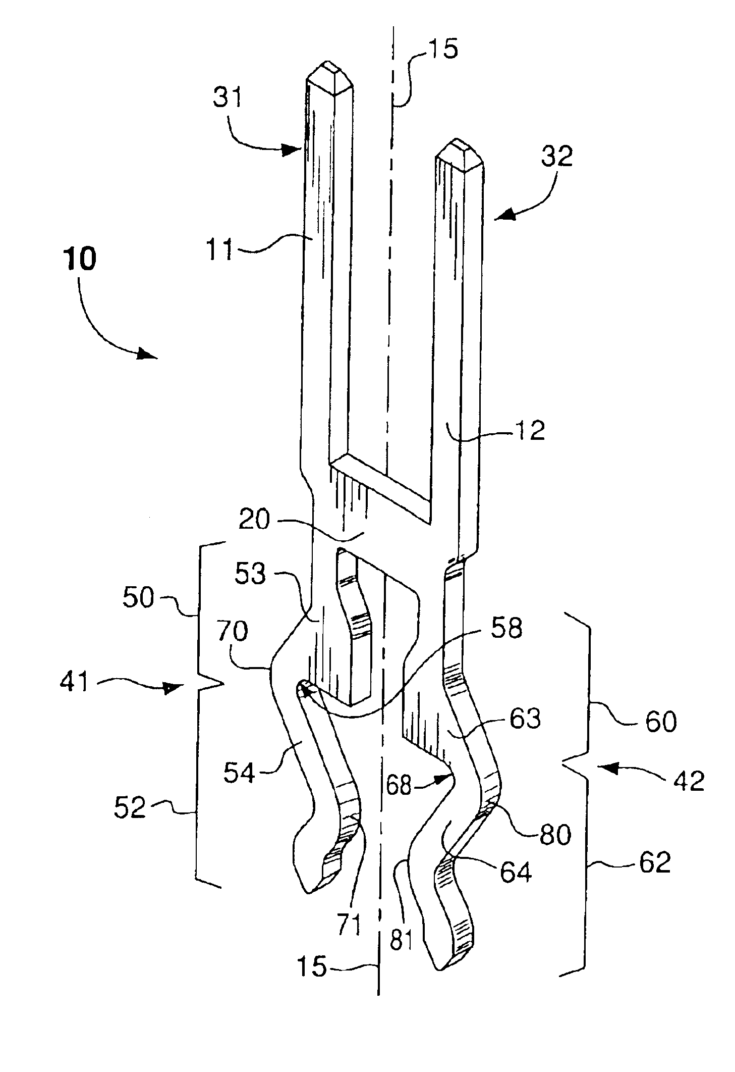
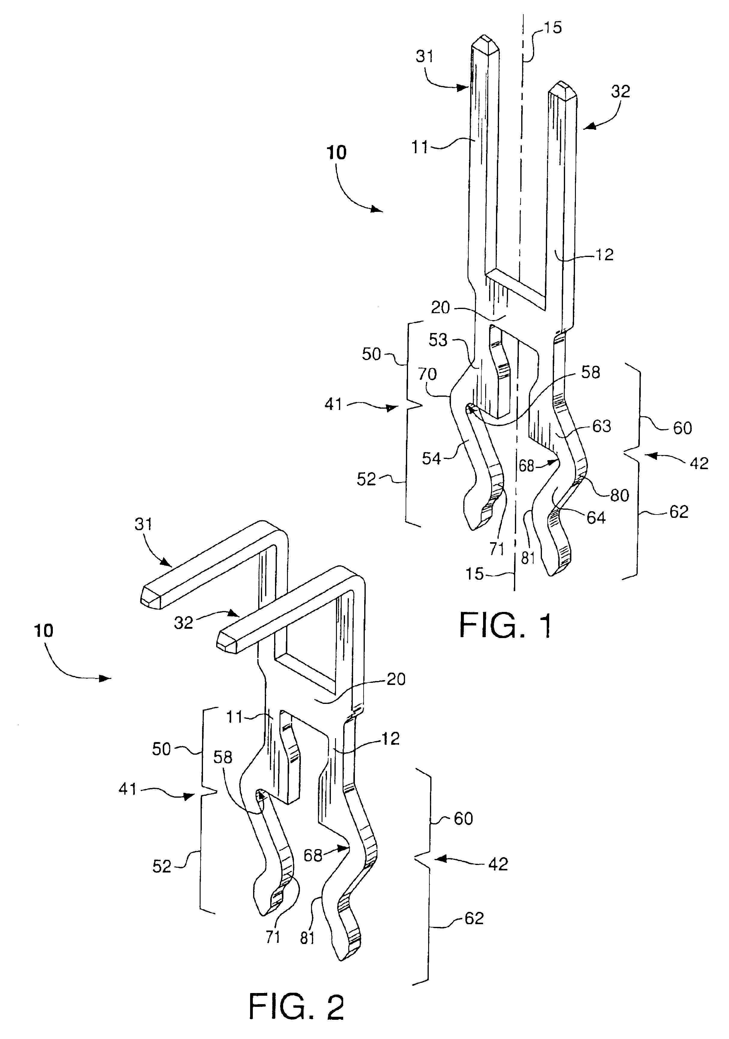
[0019]The present invention is believed to be best understood through the following detailed description of preferred embodiments and the accompanying drawings wherein like reference numbers indicate like features. Referring to FIGS. 1 and 2, an exemplary contact 10 is shown compr...


PUM


Abstract

Electrical connectors and contacts for engaging printed circuit boards are disclosed. One preferred contact has a first contact leg, a second contact leg arranged in a substantially mirror relationship with the first contact leg, and a connecting member extending between and being integral with the first contact leg and the second contact leg. Each of the contact legs includes a mating portion for insertion into a circuit board through hole. The mating portions have an elastically deformable beam for imparting a normal force onto a wall of a circuit board through hole.

Description

RELATED APPLICATION[0001]This application claims the benefit of U.S. Provisional Application No. 60 / 399,637 filed on Jul. 30, 2002.FIELD OF THE INVENTION[0002]The invention generally relates to electrical contacts and connectors. Preferred connectors are particularly useful for connecting multiple circuit boards together, and for providing electrical contact in high power applications.BACKGROUND OF THE INVENTION[0003]Electrical connectors include contacts for engaging printed circuit boards. The boards may employ holes into which contact mating portions or tails are inserted. Low insertion forces can be achieved by having larger hole dimensions relative to the dimensions of the contact tails. For a fixed arrangement, solder can be added to provide retention of the contact tails once inserted into the board holes. For a removable arrangement, solder may or may not be desirable. In the absence of solder (or a substantial amount of solder), the relative dimensions of contact tails and ...

Claims


Application Information

Patent Timeline
IPC IPC(8): H01R11/22H01R12/55H01R12/58H01R13/05H01R13/42
CPCH01R12/58H01R23/7073H01R12/737H01R23/72H01R12/712
Inventor BELOPOLSKY, YAKOVPON, RICHARD
Owner FCI AMERICAS TECH LLC
Why Eureka
Try Eureka