Method of attaching a captive panel fastener to a circuit board

Inactive Publication Date: 2005-01-27
PEM MANAGEMENT INC
View PDF6 Cites 5 Cited by
  • Summary
  • Abstract
  • Description
  • Claims
  • Application Information

AI Technical Summary

Benefits of technology

[0004] In order to meet this need in the art, the present invention has been devised in which the two main components of the panel fastener, the screw cap portion and the metal retainer portion, are assembled together after the retainer is soldered to the PCB and the retainer has cooled. The screw cap assembly is later attached to the soldered retainer by the snap action of its resilient parts. Since the screw cap is away from the heat during soldering the retainer, it cannot be adversely affected. Accordingly, the present invention provides a unique sn

Problems solved by technology

A problem arises, however, due to the soldering temperature required to affix the retainer portion of the panel fastener to the PCB because the soldering heat has an adverse effect on the materials used in the plas

Method used


Image

  • Method of attaching a captive panel fastener to a circuit board
  • Method of attaching a captive panel fastener to a circuit board
  • Method of attaching a captive panel fastener to a circuit board

Examples


Embodiment Construction

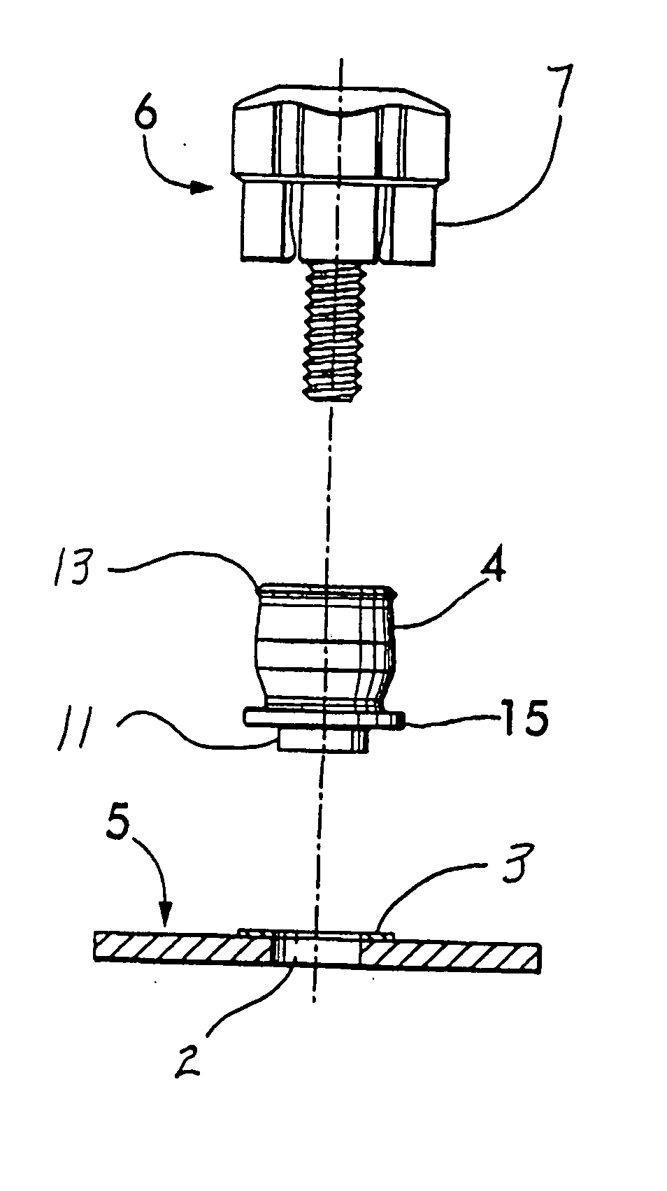
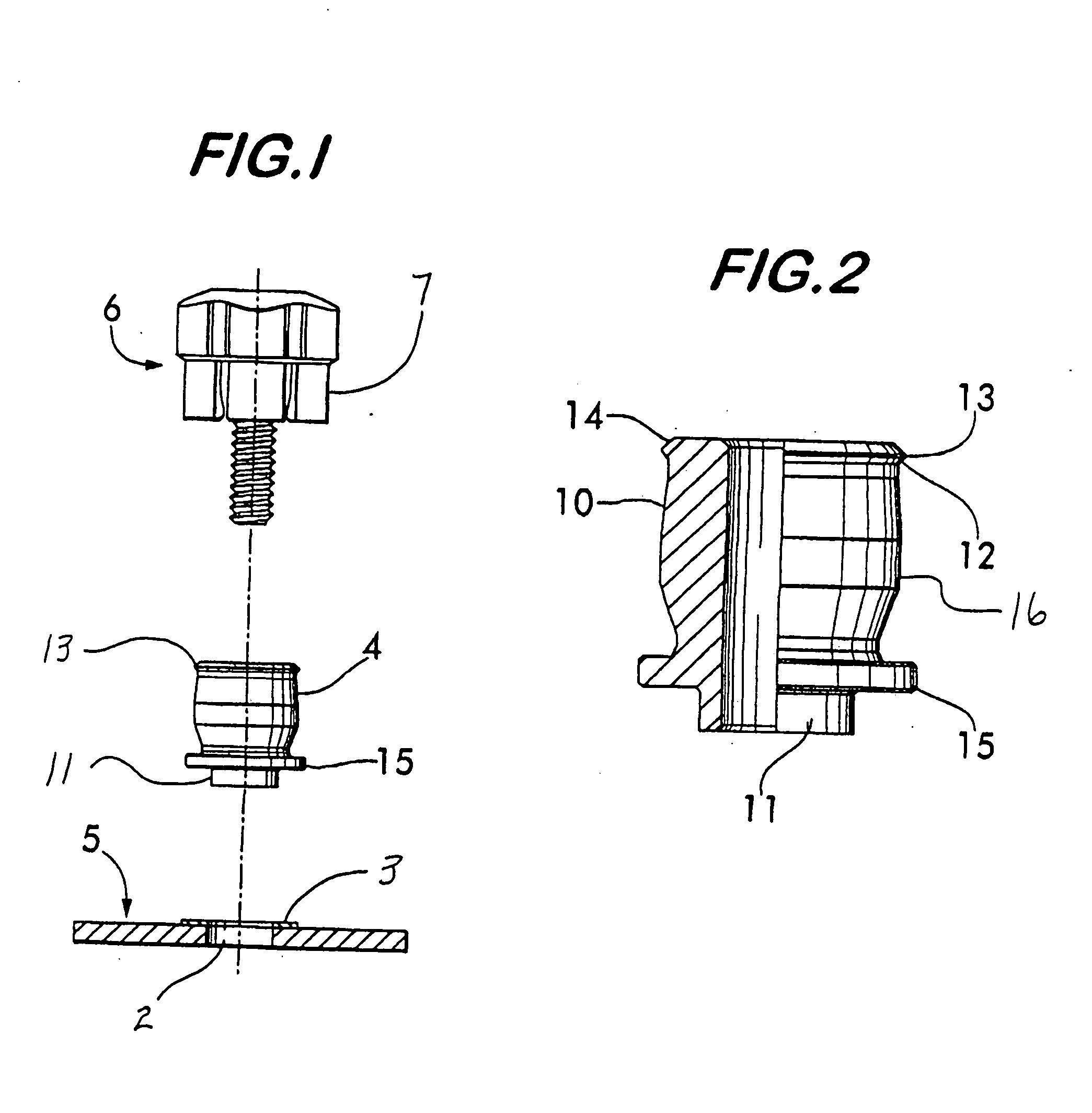
[0013] Referring now to FIG. 1, the sequence of assembly of the main components of the present invention is shown. A preform or solder paste 3 is first applied to the PCB beneath the flange 15 at the base of the barrel-shaped retainer 4. With shank 11 inserted through a hole 2 in the PCB, base flange 15 rests against the top surface of the PCB during wave or hot air soldering, providing vertical alignment and increased PCB contact surface area. After wave or hot air soldering is complete, the retainer becomes permanently attached to the PCB 5. Later, after the PCB and retainer have cooled, the screw cap assembly 6 is attached to the retainer by inserting the threaded end into the top of the retainer and pushing it downward. As the screw cap is pushed downward, the plastic fingers 7 on the screw cap deflect outwardly and snap over chamfered top flange 13.

[0014] Referring to FIG. 2, the retainer portion of the present invention is shown. It includes significant novel features which a...


PUM

PropertyMeasurementUnit
Areaaaaaaaaaaa

Abstract

A method of assembling a captive panel fastener to a printed circuit board comprises the steps of placing an axially-extending shank of a captive fastener retainer through a mounting hole in a printed circuit board, soldering the retainer to the printed circuit board, cooling the retainer, and then affixing a retractable screw assembly including a plastic screw cap to the retainer by snap attachment of the screw cap to an outside surface of the retainer.

Description

RELATED APPLICATIONS [0001] This patent application is a continuation of co-pending patent application Ser. No. 10 / 468,853 filed Aug. 25, 2003 for “Hybrid Panel Fastener with Snap-On Cap,” which is a 371 of PCT / US02 / 11378 filed Apr. 12, 2002 for “Hybrid Panel Fastener with Snap-On Cap” which claims benefit of provisional patent application Ser. No. 60 / 284,902 entitled “Hybrid Panel Fastener With Snap-On Cap” filed on Apr. 20, 2001, priority from which is hereby claimed.FIELD OF THE INVENTION [0002] The present invention relates to panel fasteners affixed to circuit boards and, in particular, to panel fasteners of the type having a molded cap composed of a material such as ABS Plastic. More specifically, it relates to panel fasteners of the type disclosed in U.S. Pat. No. 6,394,724 entitled “Snap-In Panel Fastener” which is herein incorporated by reference as though fully set forth. BACKGROUND OF THE INVENTION [0003] There are cases in which panel fasteners of the hybrid type, that i...

Claims


Application Information

Patent Timeline
IPC IPC(8): F16B5/02F16B11/00F16B37/14
CPCF16B5/0208Y10S411/999Y10S411/97Y10T29/49117Y10T29/49947Y10T29/49948Y10T29/49966Y10T29/49876Y10T29/49963F16B21/18
Inventor FRANCO, JAMES S.MCDONOUGH, WILLIAM P.
Owner PEM MANAGEMENT INC
Why Eureka
Try Eureka