Golf tee-accessory assembly

a technology for golf accessories and tees, which is applied in the field of golf accessories, can solve the problems of affecting the accuracy of golf balls, so as to achieve the effect of establishing a separation distance between the ground and the golf ball

Inactive Publication Date: 2005-06-16
NESLO DEV
View PDF18 Cites 27 Cited by
  • Summary
  • Abstract
  • Description
  • Claims
  • Application Information

AI Technical Summary

Benefits of technology

[0005] The present invention addresses the foregoing shortcomings of the prior art by providing a device for positioning a tee, on which a golf ball is placed, for contact with either a normal size or enlarged golf club head. The device comprises an elongated, hollow, cylindrical sleeve member, which can be used with any conventional golf tee of appropriate length. The hollow, cylindrical sleeve member is sized to accommodate and either snugly fit or be fixed on the shaft of a golf tee. The sleeve member is of an appropriate length selected to enable the upper end of the member closest to the ball to fit against the lower surface of the outwardly tapered head of the tee and the lower end of the member closest to the ground to engage the

Problems solved by technology

Unfortunately, the conventional golf tee leaves the height of the golf ball subject to many factors.
This introduces an undesirable level of uncertainty to the game of golf and leaves the golfer's ability to accurately hit the ball subservient to the ability of the golfer to place the tee into the ground at a consistent height due to the increased margin of error resulti

Method used


Image

  • Golf tee-accessory assembly
  • Golf tee-accessory assembly

Examples


first embodiment

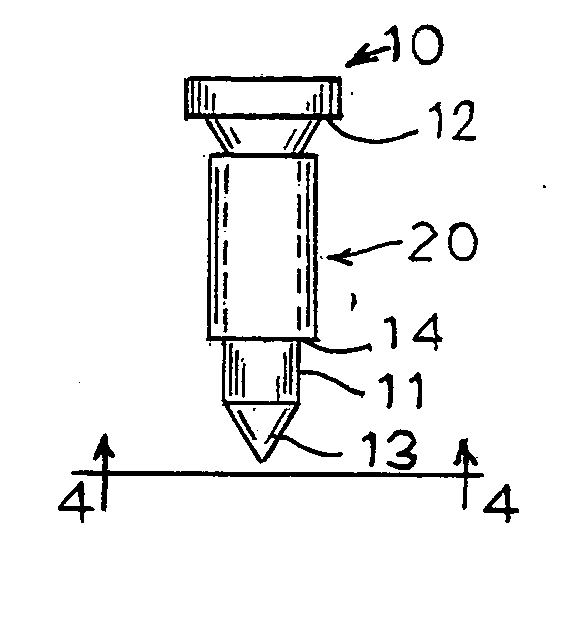
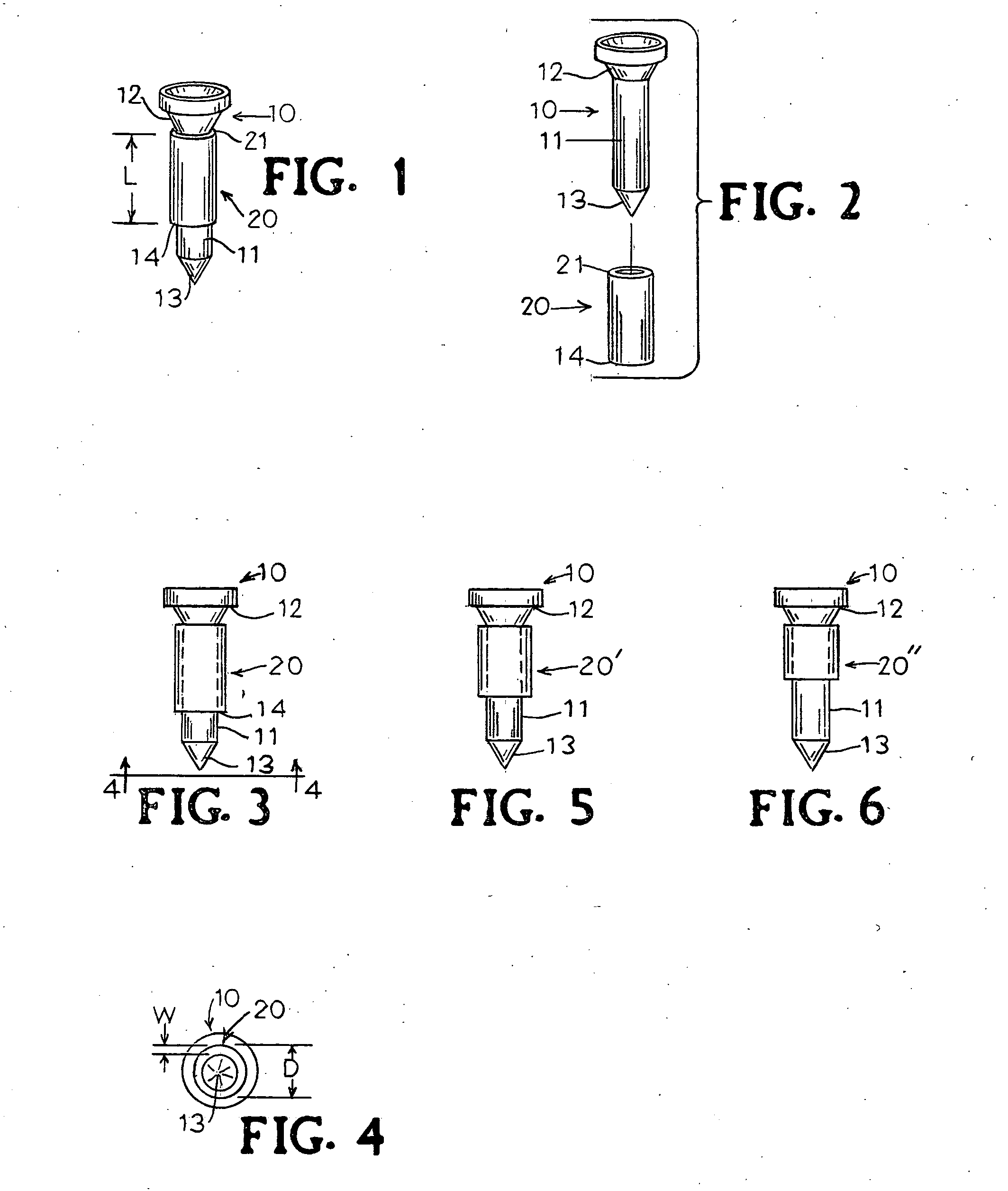
[0013]FIG. 1 is a side elevation view of a golf tee 10 with the hollow, cylindrical sleeve member 20 of the invention snugly fitted on, glued, or otherwise fixed on the shaft 11 of the tee 10. An upper end 21 of member 20 fits snugly against head 12 of the tee 10 and has a predetermined length L according to a

[0014]FIG. 2 is a side elevation view of the tee 10 separate from the member 20. The golfer moves member 20 into position onto the shaft 11 of the tee 10 by inserting the tapered end 13 of the tee 10 into the hollow upper end 21 of the member 20 and pushing until the upper end 21 encounters the head 12 of the tee 10. Alternatively, as previously stated, the sleeve member 20 can be glued, or otherwise fixed on, the shaft of the tee 10. The diameter D and wall thickness W of member 20 are sufficient to create a ground engaging area sufficient to provide noticeable resistance when a golfer places the pointed end 13 of the tee 10 into the ground and the ground comes into contact wi...

second embodiment

[0017]FIG. 5 is a side elevation view of the tee 10 that has a sleeve member 20′ of a second length according to a

third embodiment

[0018]FIG. 6 is a view of the tee 10 that has a sleeve member 20″ of a shorter third length, placing the ball closer to the ground according to a

[0019] The illustrated golf tee 10 mounting the sleeve member 20 of the invention is intended to represent any conventional tee of appropriate length. The sleeve member 20 of the invention is formed of a resilient material, preferably a hard plastic that includes a biodegradable material, such as cornstarch, and of a composition that will not mark a driver or an iron-type club. In another embodiment, the sleeve member 20 is formed of a soft plastic. Thus, the tee shaft 11 and mounting sleeve 20 will not damage either the club or the cutting blades of golf course lawnmowers when a tee is left behind. The sleeve itself may be fabricated of a color-coded plastic. In this way, the golfer can have several different height adjusted tees for a variety of golf club heads.


PUM


Abstract

A golf tee-accessory assembly for positioning a golf ball at a predetermined height, comprising a golf tee, the golf tee having upper and lower ends and a shaft of substantially uniform diameter connecting the ends, the upper end having a cup of a substantially uniform diameter for receiving a golf ball, the lower end being tapered for insertion into a playing surface; and a hollow, cylindrical sleeve member mounted on and surrounding an upper portion of the shaft of the tee, the sleeve member having a diameter and wall thickness providing, at the lower end of the sleeve, a ground-engaging surface surrounding the shaft of the tee for limiting the depth by which the lower end of the tee's shaft penetrates the ground.

Description

BACKGROUND OF THE INVENTION [0001] This present invention relates to golf equipment. More particularly, this invention pertains to an improved tee for vertically positioning a golf ball prior to contact with a club head. It is recognized that the height of a golf ball from the ground with respect to the club head affects both the height and the distance of the golf shot. Once a golfer has determined, by practice, which height is desirable to have the ball from the ground, it is ideal to keep that height consistent from one hole to the next. [0002] Unfortunately, the conventional golf tee leaves the height of the golf ball subject to many factors. These include “eyeing” the height of the ball, using one's knuckles to gauge the distance of the top of the tee to the ground, the presence of grass obscuring the ground, and the composition of the soil. This introduces an undesirable level of uncertainty to the game of golf and leaves the golfer's ability to accurately hit the ball subserv...

Claims


Application Information

Patent Timeline
IPC IPC(8): A63B22/00A63B57/00
CPCA63B2225/093A63B57/0018A63B57/10
Inventor OLSEN, JAMES L.
Owner NESLO DEV
Why Eureka
Try Eureka