Optical information recording medium
a technology of optical information and recording medium, which is applied in the direction of record information storage, flat record carrier containers, instruments, etc., can solve the problems of optical information recording medium warpag
- Summary
- Abstract
- Description
- Claims
- Application Information
AI Technical Summary
Benefits of technology
Problems solved by technology
Method used
Image

Examples
embodiment 1
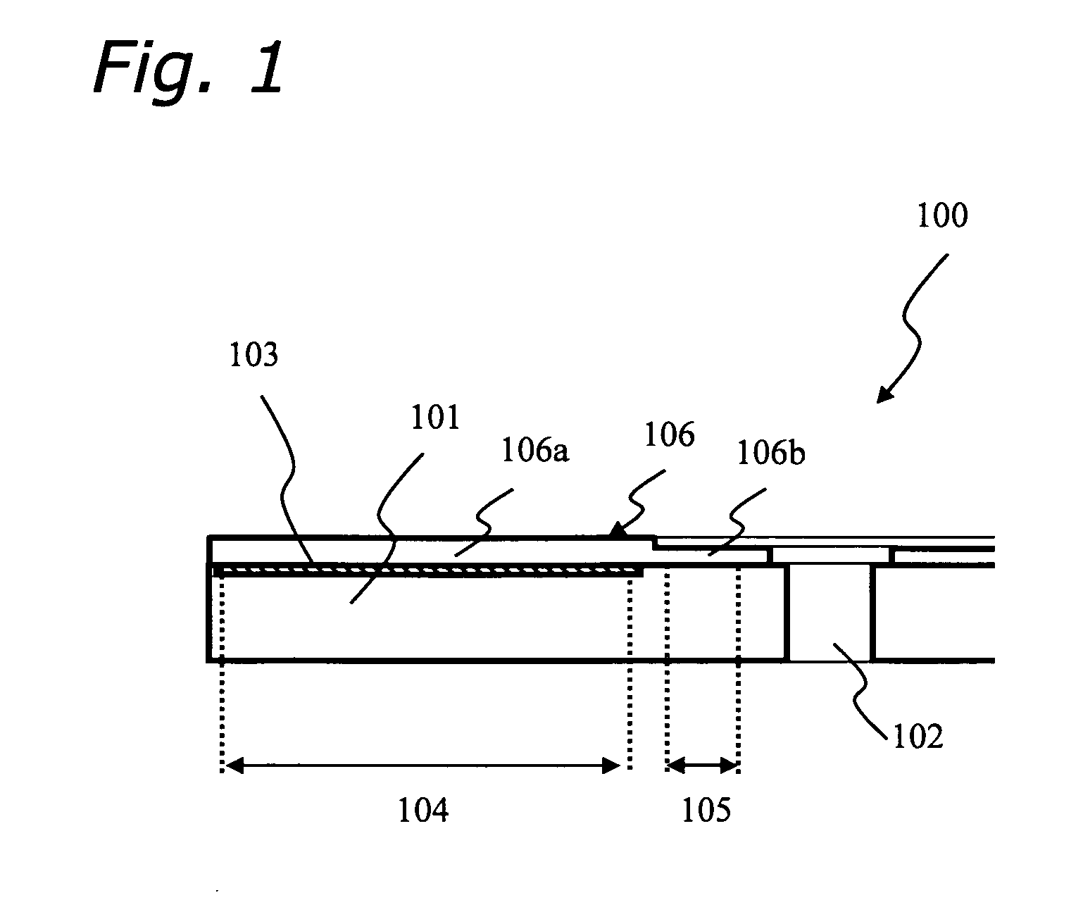
[0047]FIG. 1 is an explanatory diagram showing an optical information recording medium 100 of the present invention. FIG. 1 shows a brief overview of the optical information recording medium 100 of the present invention. The medium 100 comprises an information recording layer 103 and a light-transmitting layer 106 on a main surface of a substrate 101 having a center hole 102. An information recording area 104 is an annular area on the substrate 101, where the information recording layer 103 is formed. In addition, an area formed at an inner area beyond an innermost circumference of the information recording area 104, where the medium 100 is clamped, is defined as a clamp area 105. The information recording area 104 and the clamp area 105 are neither overlapped nor contacted, and an annular area is formed between those areas. The light-transmitting layer 106 is formed to cover the information recording layer 103 at the information recording area 104 and also to cover the substrate 10...
example 1
[0051] Below, structures of an optical information recording medium based on a conventional technique and of the present invention are compared. Note that, FIG. 2 through FIG. 5 show the conventional technique, and FIG. 6 shows the present invention.
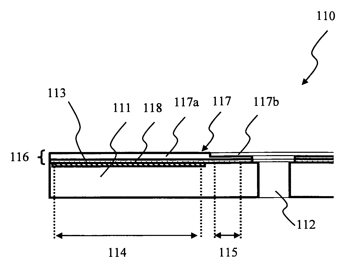
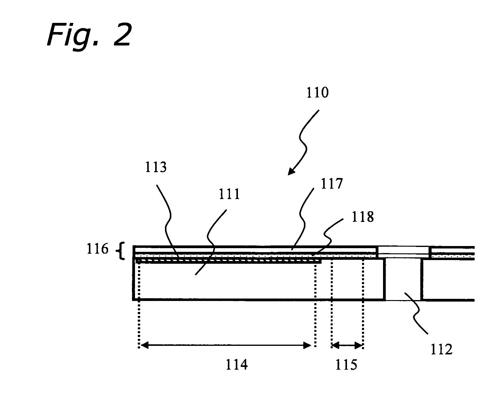
[0052] As shown in FIG. 6, the optical information recording medium 110 comprises a substrate 111, an information recording layer 113 and a transmitting layer 116. The substrate 111 has a thickness of approximately 1.1 mm and a diameter of approximately 120 mm, and is made of polycarbonate applied by an injection molding method. The information recording layer 113 comprises a guide-groove with a depth of approximately 20 nm formed on the substrate 111 and a recording film which contains phase-changeable materials or dielectric materials formed on the guide-groove. The transmitting layer 116 is formed on the information recording layer 113 of the substrate 111 and comprises a sheet substrate 117 with a thickness of approximately 70 μm an...
example 2
[0067] Below, structures of an optical information recording medium based on a conventional technique and of the present invention are compared. For descriptions which correspond to Example 1, overlapping explanations may be omitted. Note that, FIG. 7 and FIG. 8 show the conventional technique, and FIG. 9 shows an embodiment of the present invention.
[0068] In FIG. 9(a), an optical information recording medium 200 of the present invention is shown. In the medium 200 in FIG. 9, a substrate 201 was employed, which was the same as the substrate of Example 1, and a light-transmitting layer 206 was formed only of radiation-setting resin.
[0069] Here, in the light-transmitting layer 206 of the medium 200 of the present invention, the average thickness of a second region 206b corresponding to the clamp area is thinner than an average thickness of a first region 206a corresponding to the information recording area.
[0070] Note that, in the structure of the conventional technique shown in FI...
PUM
 Abstract
Description
Claims
Application Information
 - R&D
- Intellectual Property
- Life Sciences
- Materials
- Tech Scout
- Unparalleled Data Quality
- Higher Quality Content
- 60% Fewer Hallucinations
Browse by: Latest US Patents, China's latest patents, Technical Efficacy Thesaurus, Application Domain, Technology Topic, Popular Technical Reports.
© 2025 PatSnap. All rights reserved.Legal|Privacy policy|Modern Slavery Act Transparency Statement|Sitemap|About US| Contact US: help@patsnap.com