Optical information recording medium, producing method thereof and method of recording/erasing/reproducing information

a technology of optical information and recording medium, applied in the field of optical information recording medium, can solve the problems of readout error, phase change optical recording medium, and higher error rate of recording signal

Inactive Publication Date: 2000-11-28
PANASONIC CORP
View PDF17 Cites 88 Cited by
  • Summary
  • Abstract
  • Description
  • Claims
  • Application Information

AI Technical Summary

Problems solved by technology

However, it is known that the phase change optical recording medium has the following problems.
That is, the signal is repeatedly rewritten, thereby the reflectance of the medium is reduced, an amplitude of the signal is gradually reduced, or a jitter value at a marked position of a recording mark becomes larger, thereby an error rate of the recording signal becomes higher.
Therefore, when the signal is reproduced, a readout error is occurred.
Accordingly, there is such a problem that a possible times of rewriting is limited.
Furthermore, another cause is that one part of the protective layer material is chemically reacted with the recording layer.
For example, under an environment having a high temperature and a high humidity, there is another problem that a peeling is occurred.
Thereby, there is further problem that oxide such as SiO.sub.2, Ta.sub.2 O.sub.5, Al.sub.2 O.sub.3 and the like and nitride such as Si.sub.3 N.sub.4, AlN and the like cannot be applied to a dielectric layer material.
Furthermore, when the nitrogen partial pressure in the sputter gas gets too high, much surplus nitrogen exists in the film, thereby similarly to the above case, the bet

Method used


Image

  • Optical information recording medium, producing method thereof and method of recording/erasing/reproducing information
  • Optical information recording medium, producing method thereof and method of recording/erasing/reproducing information
  • Optical information recording medium, producing method thereof and method of recording/erasing/reproducing information

Examples


example 2

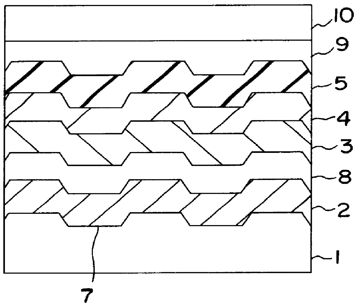
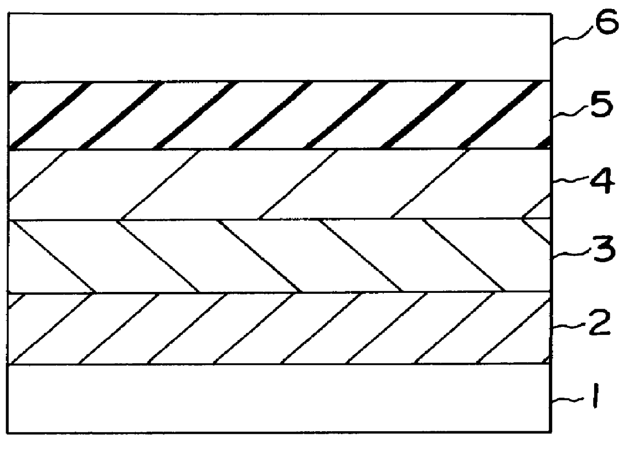
All the protective layers at the substrate side of the disk (1) in the table 4 in the example 1 are changed to the Ge--N layer or the Ge--N--O layer, thereby a disk (5) is formed (accordingly, the Ge--N protective layer or the Ge--N--O protective layer whose thickness is 91 nm is formed at the substrate side of the recording layer). Furthermore, all the protective layers at the reflecting layer side of the disk (3) in the table 4 are changed to the Ge--N layer or the Ge--N--O layer, thereby a disk (6) is formed (accordingly, the Ge--N protective layer or the Ge--N--O protective layer whose thickness is 25.2 nm is formed at the reflecting layer side of the recording layer). The repeating characteristic of disks (5) and (6) is examined by the same method as the example 1. Both of them can similarly obtain the result .circleincircle.. That is, the Ge--N layer or the Ge--N--O layer can be formed in such a manner that the Ge--N layer or the Ge--N--O layer can obtain a thickness necessary...

example 3

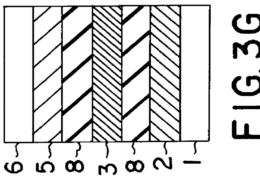
Next, the recording layer 3 comprises a phase change material whose main component is a Ge2Sb2.3Te5 alloy, when the barrier layer 8 is formed, Sb is used as the target, and the mixture of Ar and nitrogen is used as the sputter gas. On the above condition, the films comprising the structure shown in FIGS. 3A and 3B are formed (a disk (2), a disk (4)). In this case, the film thickness of each layer is same as the thickness in the above case that Ge is used as the target. The spatter gas pressure of the barrier layer 8 is 20 mTorr, and the partial pressure ratio of Ar to nitrogen in the sputter gas is 3 to 1. In this case, the result of the repeating characteristic is shown in disk numbers (2) and (4) in the table 4.

According to the table 4, compared to the case that Ge is used as the target so that the film is formed, although the number of repeatable times is inferior, better repeating characteristic can be obtained than the comparative example.

example 4

Next, when the layer structure is constructed as shown in FIG. 3A, and Ge is used as the target for forming the barrier layer 8, the range of the film formation condition which can obtain a better characteristic is examined.

According to the embodiment, the total sputter gas pressure is constantly set to 20 mTorr, and the partial pressure ratio of Ar and nitrogen in the sputter gas has three kinds of ratio, that is, 2:1, 1:1 and 1:2. The sputter power of Ge is RF100W, 300W, 500W, 700W, 710W, 750W, 1 kW, 1.5 kW and 2 kW. That is, since the target is the disc whose diameter is 10 cm, when the sputter power is converted into the power density, the respective sputter powers are changed to 1.27W / cm.sup.2, 3.82W / cm.sup.2, 6.37W / cm.sup.2, 8.91W / cm.sup.2, 9.04W / cm.sup.2, 9.55 kW / cm.sup.2, 12.7 kW / cm.sup.2, 19.1 kW / cm.sup.2 and 25.5 W / cm.sup.2, respectively. Thereby, the film is formed, and the characteristic of the disks is examined. When the partial ratio of Ar and nitrogen is changed to 2:...


PUM

PropertyMeasurementUnit
Pressureaaaaaaaaaa
Pressureaaaaaaaaaa
Poweraaaaaaaaaa

Abstract

In a phase-change recording medium, a recording medium is provided with a barrier layer including Ge-N, Ge-N-O between a recording layer and a dielectric protective layer in order to prevent a chemical reaction and an atom diffusion between the recording layer and the dielectric protective layer. A barrier material can be also applied to the protective layer itself. Thereby, it is possible to considerably suppress a reduction of a reflectivity and a reduction of a signal amplitude due to the repeat of recording and erasing, such reductions being observed in a conventional phase-change optical information recording medium, and thereby the number of overwriting times can be increased.

Description

1. Field of the InventionThe present invention relates to an optical information recording medium provided with an optically detectable information recording layer, the producing method thereof and a method of recording / erasing / reproducing information.2. Description of the Prior ArtA recording material thin film layer comprising a metal thin film and an organic thin film is formed on a disc-shaped or a card-shaped substrate. A high energy beam focused on a micro light spot having a submicron order diameter is irradiated onto the recording material layer, thereby a local variation is generated on recording material layer. Thereby, such a technique that an information signal is stored is already well known. More specifically, when an optical magnetic material thin film and a phase change material thin film are used for a recording layer, it is easy to rewrite the signal. Accordingly, this technique has been actively studied and developed. For example, in case of the optical magnetic r...

Claims


Application Information

Patent Timeline
IPC IPC(8): G11B7/257G11B7/26G11B7/243G11B7/24G11B7/007G11B7/004G11B7/0045G11B7/0055G11B7/006G11B7/2433G11B7/254G11B7/2578
CPCG11B7/24G11B7/243G11B7/257G11B7/26G11B7/00557G11B7/00454G11B2007/25715G11B7/006G11B7/0062G11B7/00718G11B7/266G11B2007/24312G11B2007/24314G11B2007/24316G11B2007/2571G11B2007/25713G11B7/2578G11B7/2433
Inventor YAMADA, NOBORUOTOBA, MAYUMINAGATA, KENICHIKAWAHARA, KATSUMI
Owner PANASONIC CORP
Why Eureka
Try Eureka