Current cutoff circuit and electric steering wheel lock

a current cutoff circuit and electric steering wheel technology, applied in the direction of anti-theft devices, dc motor rotation control, instruments, etc., can solve the problem of unanticipated excessive current flowing through the motor circuit, and achieve the effect of preventing overheating a load

Active Publication Date: 2005-06-23
KK TOKAI RIKA DENKI SEISAKUSHO
View PDF6 Cites 19 Cited by
  • Summary
  • Abstract
  • Description
  • Claims
  • Application Information

AI Technical Summary

Benefits of technology

[0005] The present invention provides a current cutoff circuit and an electric steering wheel lock that prevents overheating of a load.

Problems solved by technology

However, in such type of relay 53, unanticipated excessive current may flow though the motor circuit.

Method used


Image

  • Current cutoff circuit and electric steering wheel lock
  • Current cutoff circuit and electric steering wheel lock
  • Current cutoff circuit and electric steering wheel lock

Examples


Embodiment Construction

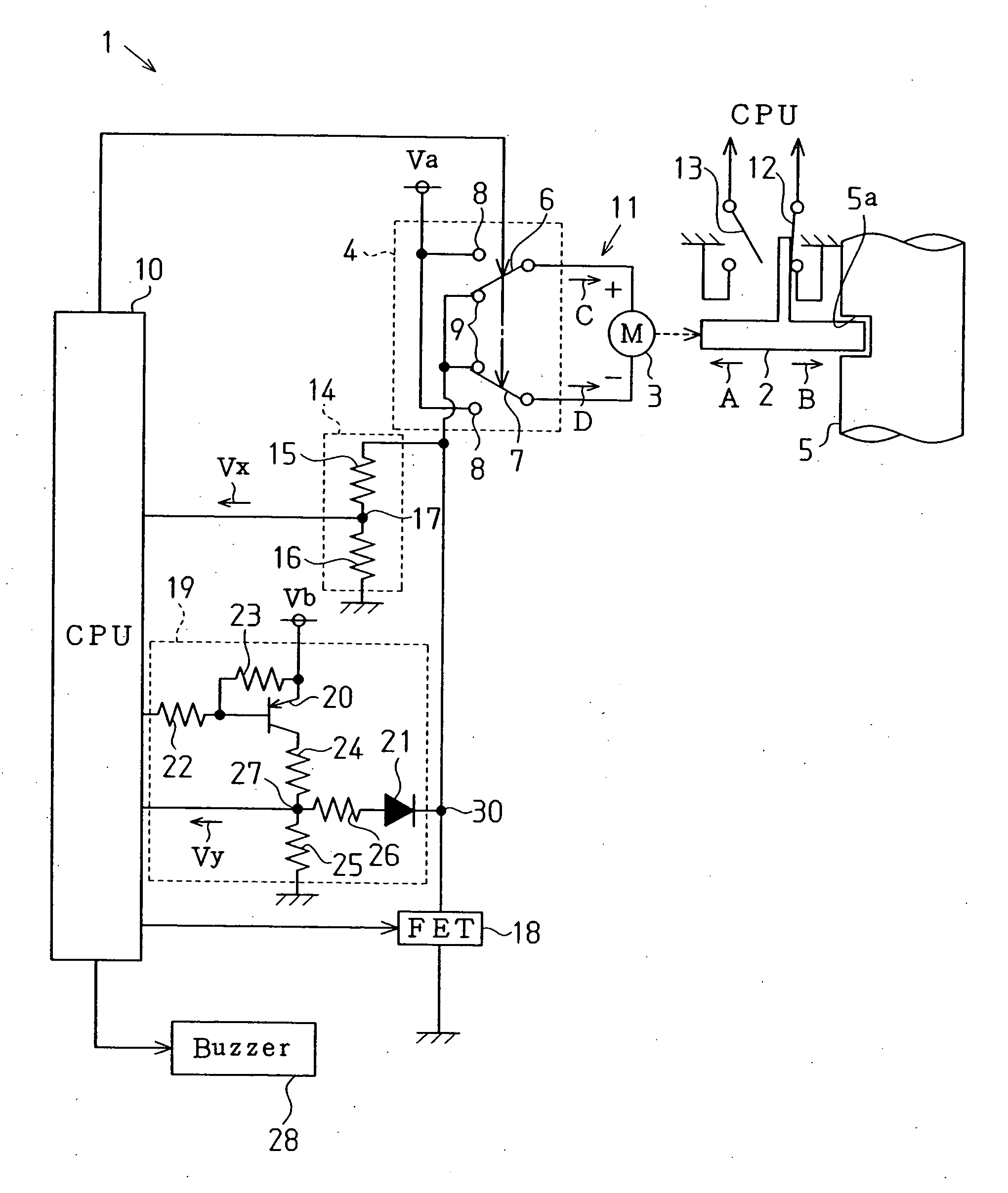
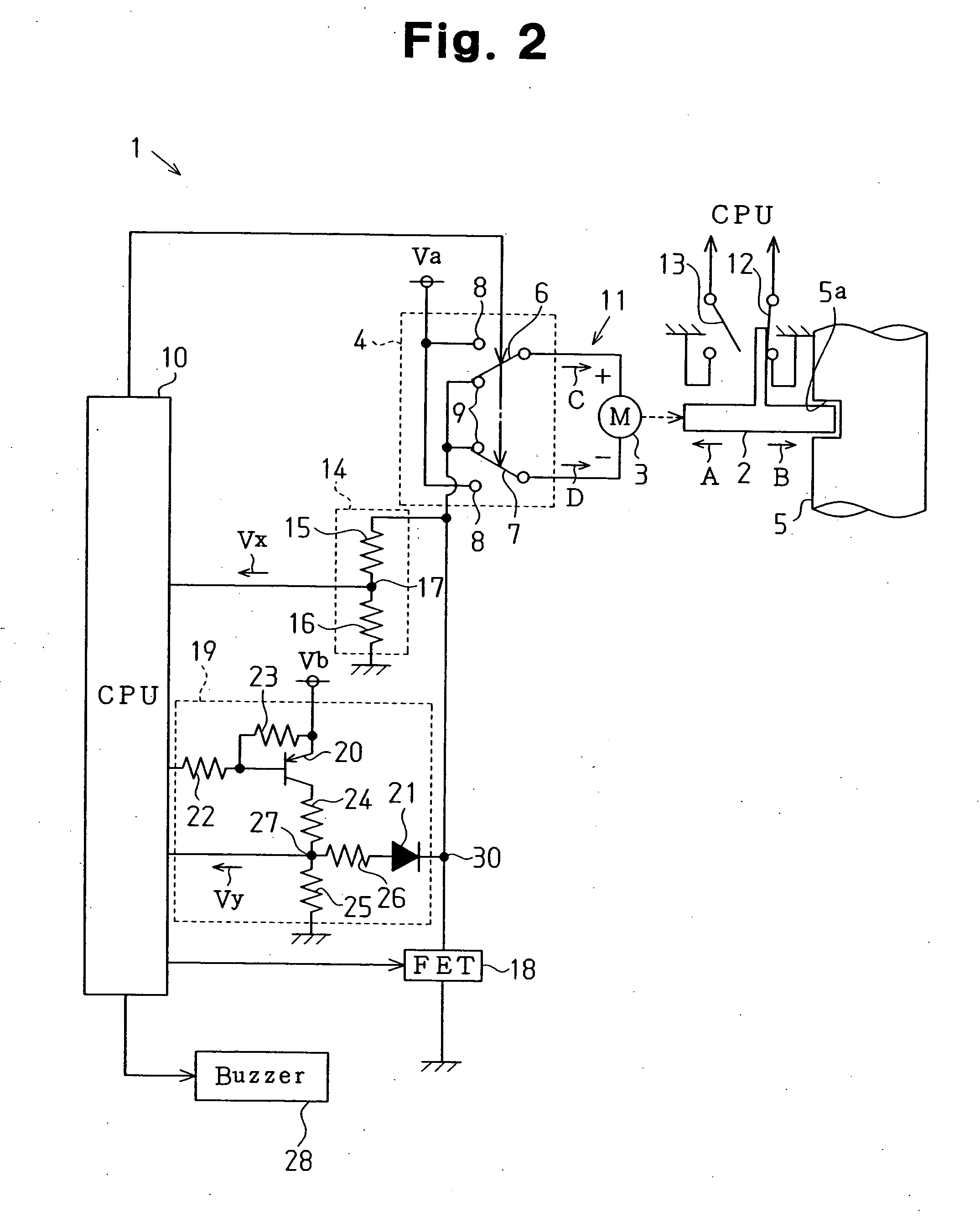
[0014] An electric steering wheel lock 1 according to a preferred embodiment of the present invention will now be described with reference to FIGS. 2 and 3.

[0015]FIG. 2 is a schematic diagram showing the electric configuration of the steering wheel lock 1. The steering wheel lock 1 is installed in an automobile to restrict rotation of a steering shaft 5 such as when the automobile is parked. The steering wheel lock 1 includes a lock bar 2, a motor 3 functioning as a drive source of the lock bar 2, and a relay 4 for switching the operation state of the motor 3. The motor 3 moves the lock bar 2 in the direction of arrow A in FIG. 2 (movement direction of the lock bar 2 away from the steering shaft 5) and in the direction of arrow B in FIG. 2 (movement direction of the lock bar 2 toward the steering shaft 5). The steering wheel lock 1 serves as a load control circuit, the motor 3 serves as a load (drive unit), and the relay 4 serves as a switching unit.

[0016] A groove 5a is formed in...


PUM


Abstract

An electric cutoff circuit for preventing overheating of a load. The current shutoff circuit includes an FET connected to a motor circuit. A relay fault detection circuit is connected to the motor circuit to detect potential at the motor circuit. A CPU sends a control signal to a relay. The CPU determines whether a fault has occurred in the relay based on the control signal sent to the relay and the detection of the relay fault detection circuit. When determining that a fault has occurred in the relay, the CPU opens the FET to configure an open circuit with the motor circuit.

Description

BACKGROUND OF THE INVENTION [0001] The present invention relates to a current cutoff circuit and an electric steering wheel lock that prevents a load from overheating. [0002] Steering wheel locks are installed in automobiles to prevent automobile theft in the prior art. A typical steering wheel lock is an electric steering wheel lock 51 such as that shown in FIG. 1. The steering wheel lock 51 includes a central processing unit (CPU) 52, a relay 53 controlled by the CPU 52, a motor 55 connected to the relay 53, and a lock bar 54 that engages a steering shaft (not shown) and that is moved by the motor 55. The relay 53 includes a switch 56 connected to the positive terminal of the motor 55 and a switch 56 connected to the negative terminal of the motor 55. The switches 56 and 57 each have a contact switched between a battery terminal 58a and a ground terminal 58b. [0003] As shown in the state of FIG. 1, current does not flow to the motor 55 and the lock bar 54 does not move when the co...

Claims


Application Information

Patent Timeline
Patent Type & Authority Applications(United States)
IPC IPC(8): B60R25/0215B60R25/24G05F1/573H02H7/085H02P7/06
CPCB60R25/02153H02P7/29H02P7/0044H02P7/04Y10T70/5956
Inventor NAGAE, TOSHIHIROOTANI, KAZUYAMAEDA, TORU
Owner KK TOKAI RIKA DENKI SEISAKUSHO
Why Eureka
Try Eureka