
Magnetic stimulators and coils therefor

a magnetic stimulation and coil technology, applied in the field of magnetic stimulation stimulators, can solve the problem of significant non-uniform current density through the solid body of the coil

Active Publication Date: 2005-06-23
THE MAGSTIM
View PDF2 Cites 28 Cited by
  • Summary
  • Abstract
  • Description
  • Claims
  • Application Information

AI Technical Summary

Problems solved by technology

At this comparatively high frequency, owing to the electrical phenomena known as the skin and proximity effects, there is a very significant non-uniformity in the current density through the solid body of the coil.

Method used


Image

  • Magnetic stimulators and coils therefor
  • Magnetic stimulators and coils therefor
  • Magnetic stimulators and coils therefor

Examples


Embodiment Construction

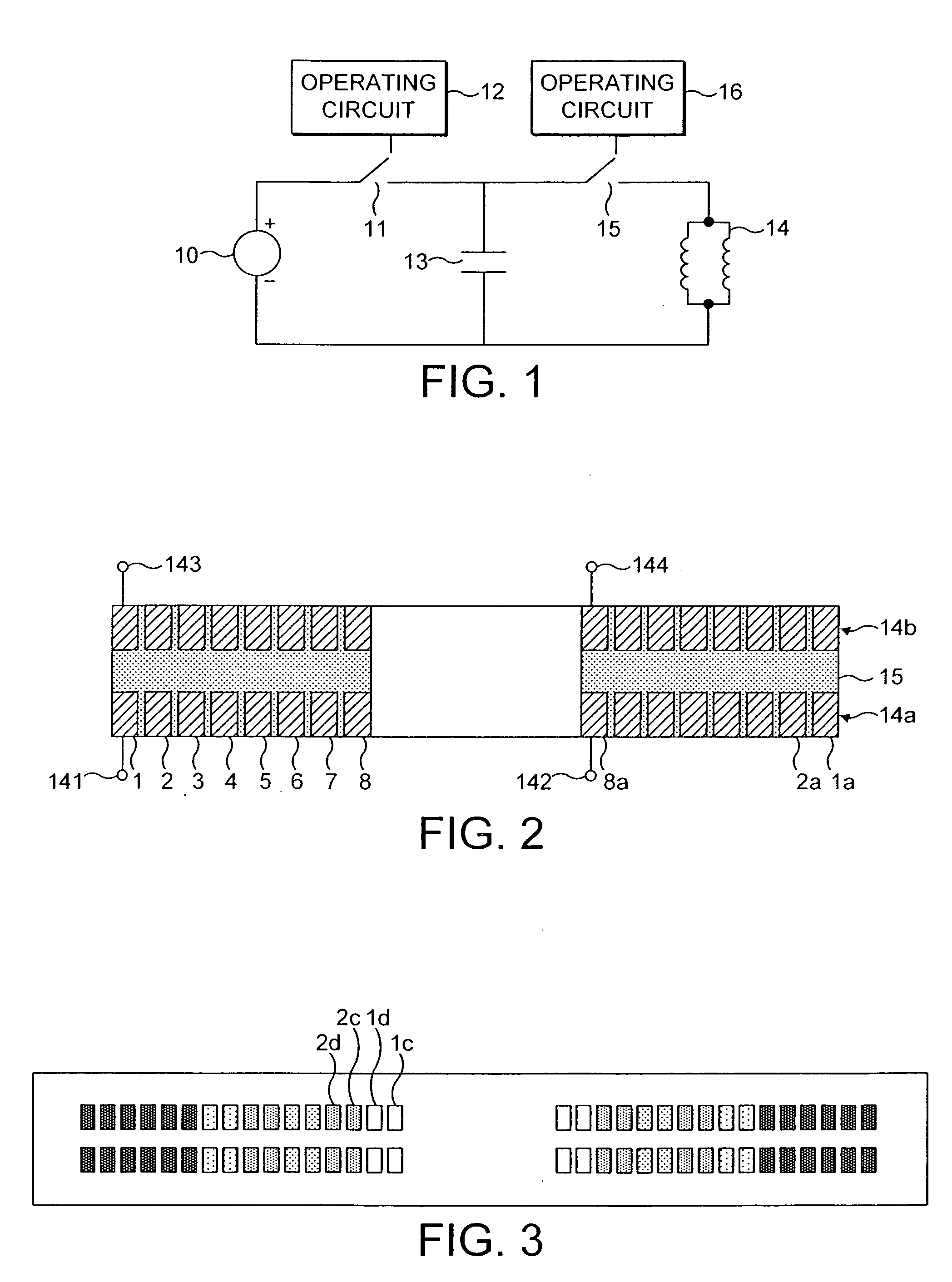
[0015]FIG. 1 of the drawings illustrates in a rather simplified manner one example of the electrical circuit of a magnetic stimulator according to the invention.

[0016] A direct current source 10 is connectable by way of a switch 11, under the control of an operating circuit 12, to charge a capacitor 13. This capacitor, hereinafter called the discharge capacitor, can be controllably discharged into a coil 14 by closure of a switch 15 under the control of an operating circuit 16. The resistance of the coil 14 is not shown explicitly in FIG. 1.

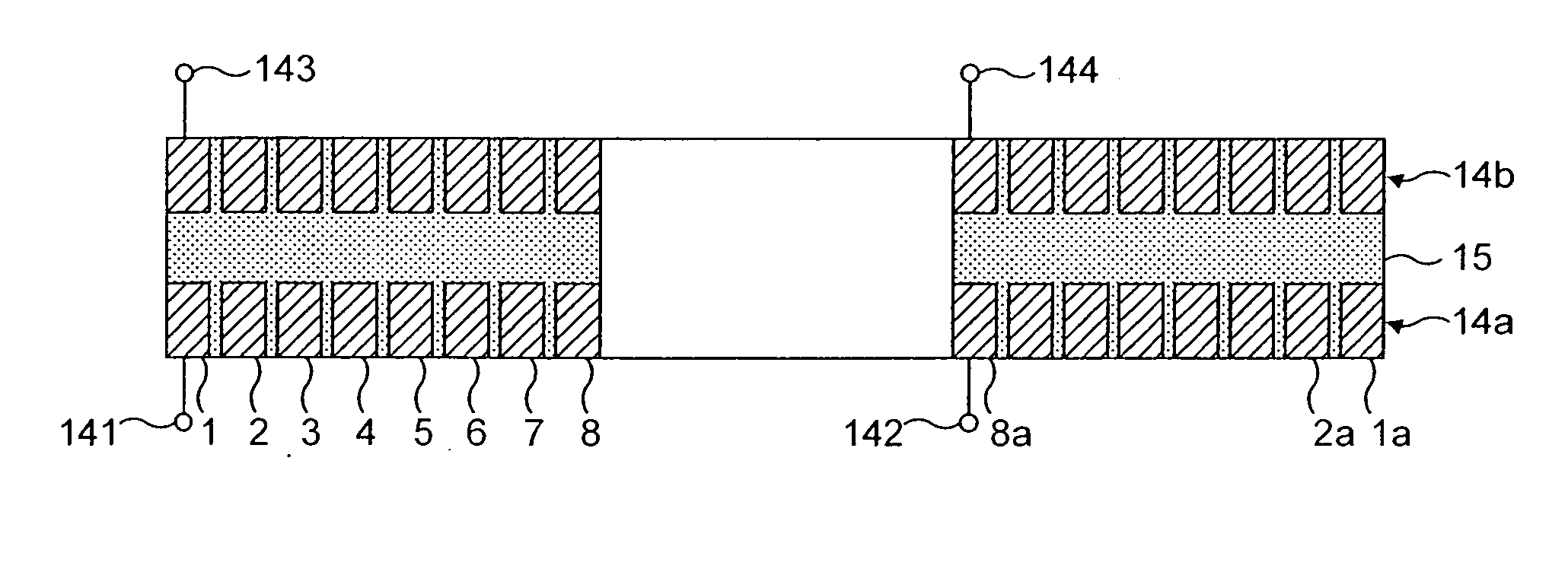
[0017] As will be more particularly described with reference to FIG. 2, the coil 14 comprises a plurality of similar face-to-face coil windings separated by a substantial gap. The coils may be in series or parallel though should produce additive magnetic fields.

[0018] In practice the charging circuit, namely source 10, switch 11 and capacitor 13 and the discharge circuit, namely capacitor 13, switch 15 and coil 14, are substantially more compl...


PUM


Abstract

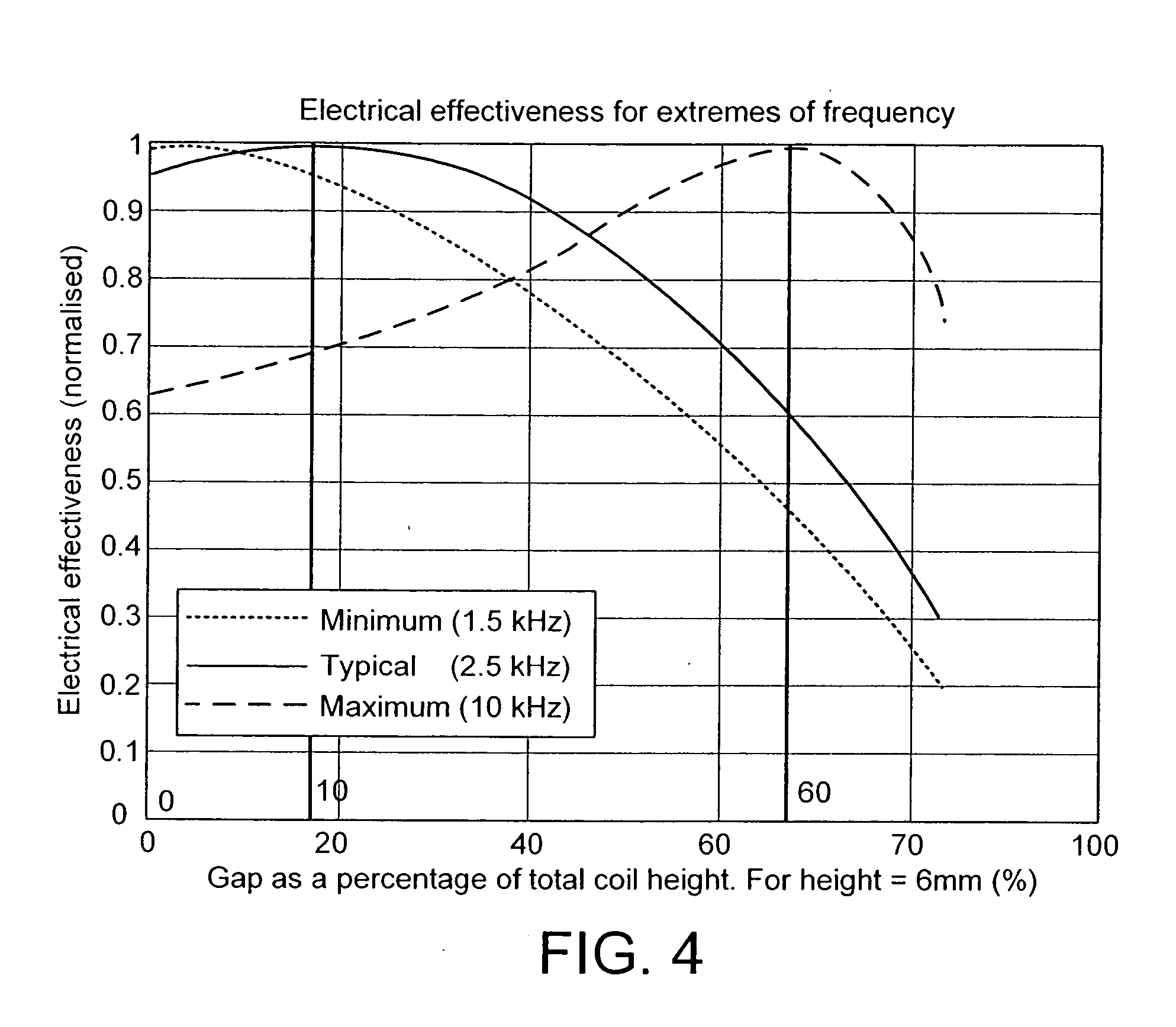
A magnetic coil inductor for use in magnetic stimulators comprises two face-to-face electrically connected windings each having a multiplicity of turns of a respective conductor. Corresponding turns are separated by a gap which typically is of the order of 18 to 20% of the total height of the coil. The magnetic stimulator includes a discharge capacitor and a switch arrangement operable to provide discharge pulses at a selected repetition rate through the inductor, the inductor and the capacitor constituting a resonant circuit of which the resonant frequency is substantially in excess of the repetition rate and is typically between 2 and 6 kHz.

Description

FIELD OF THE INVENTION [0001] The present invention relates to magnetic stimulators, primarily intended for the magnetic stimulation of neuro-muscular tissue. The invention more particularly relates to an improved coil for use in such magnetic stimulation and stimulators including such coils. GENERAL BACKGROUND [0002] Known magnetic stimulators comprise generally a charging circuit, a capacitor, a large magnetic coil and a control for allowing discharge of the capacitor through the coil. The ‘stimulating’ coil is usually of a size adapted to fit partly over a human cranium. [0003] The discharge capacitor may be discharged, normally by means of a switch in series between the capacitor and the coil or, in more sophisticated embodiments, by electronic switches such as thyristors which not only allow discharge of the capacitor through the coil but also facilitate the recovery of electrical energy by the capacitor from the stimulating coil. One suitable arrangement for this purpose is de...

Claims


Application Information

Patent Timeline
Patent Type & Authority Applications(United States)
IPC IPC(8): A61N2/02
CPCA61N2/02
Inventor MYERS, ANNA M.BARKER, ANTHONY T.HOSE, DAVID R.
Owner THE MAGSTIM
Learn More