Standing wave particle beam accelerator

a particle beam accelerator and standing wave technology, applied in accelerators, klystrons, electric discharge tubes, etc., can solve the problems of not being able to achieve the prescribed/desirable level of output radiation yield associated with the generated electron beam, adding substantial weight to existing accelerators,

Inactive Publication Date: 2005-06-23
VARIAN MEDICAL SYSTEMS
View PDF25 Cites 24 Cited by
  • Summary
  • Abstract
  • Description
  • Claims
  • Application Information

AI Technical Summary

Problems solved by technology

However, existing accelerators may not be able to generate electron beams having all these characteristics.
For example, while an accelerator may generate an electron beam having a desirable cross sectional dimension, the output radiation yield associated with the generated electron beam may not reach a prescribed / desirable level.
Use of external solenoids adds substantial weight to existing accelerators, increases cost of manufacturing, and makes it difficult to maneuver the accelerators (especially when the accelerator is being used to perform testing).
However, such electron sources increase the size and weight of the overall accelerator, and complicate design and operation of the accelerator.
Generally, the higher the injection voltage used, the more effort is required to ensure personnel safety.

Method used


Image

  • Standing wave particle beam accelerator
  • Standing wave particle beam accelerator
  • Standing wave particle beam accelerator

Examples


example

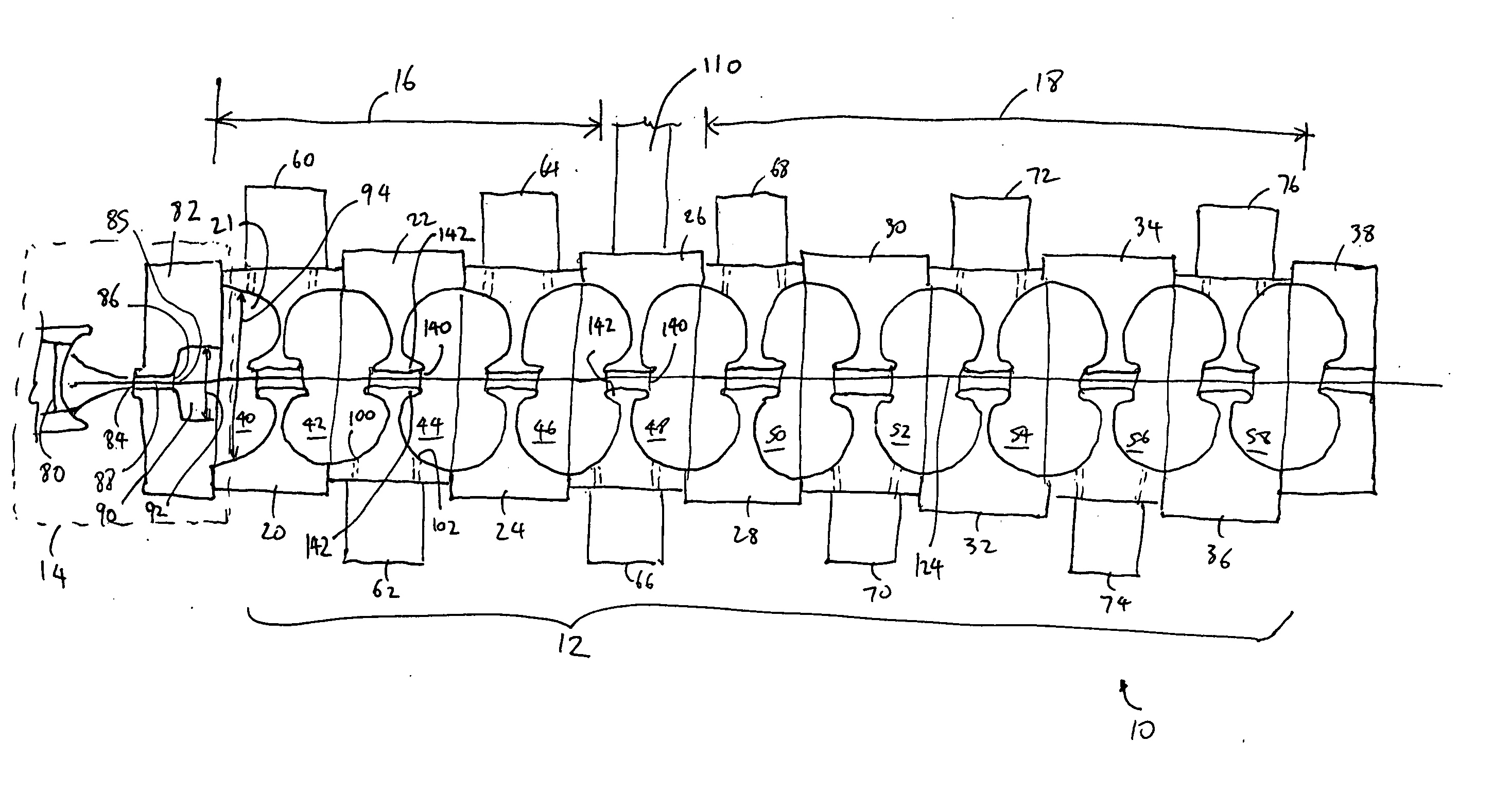
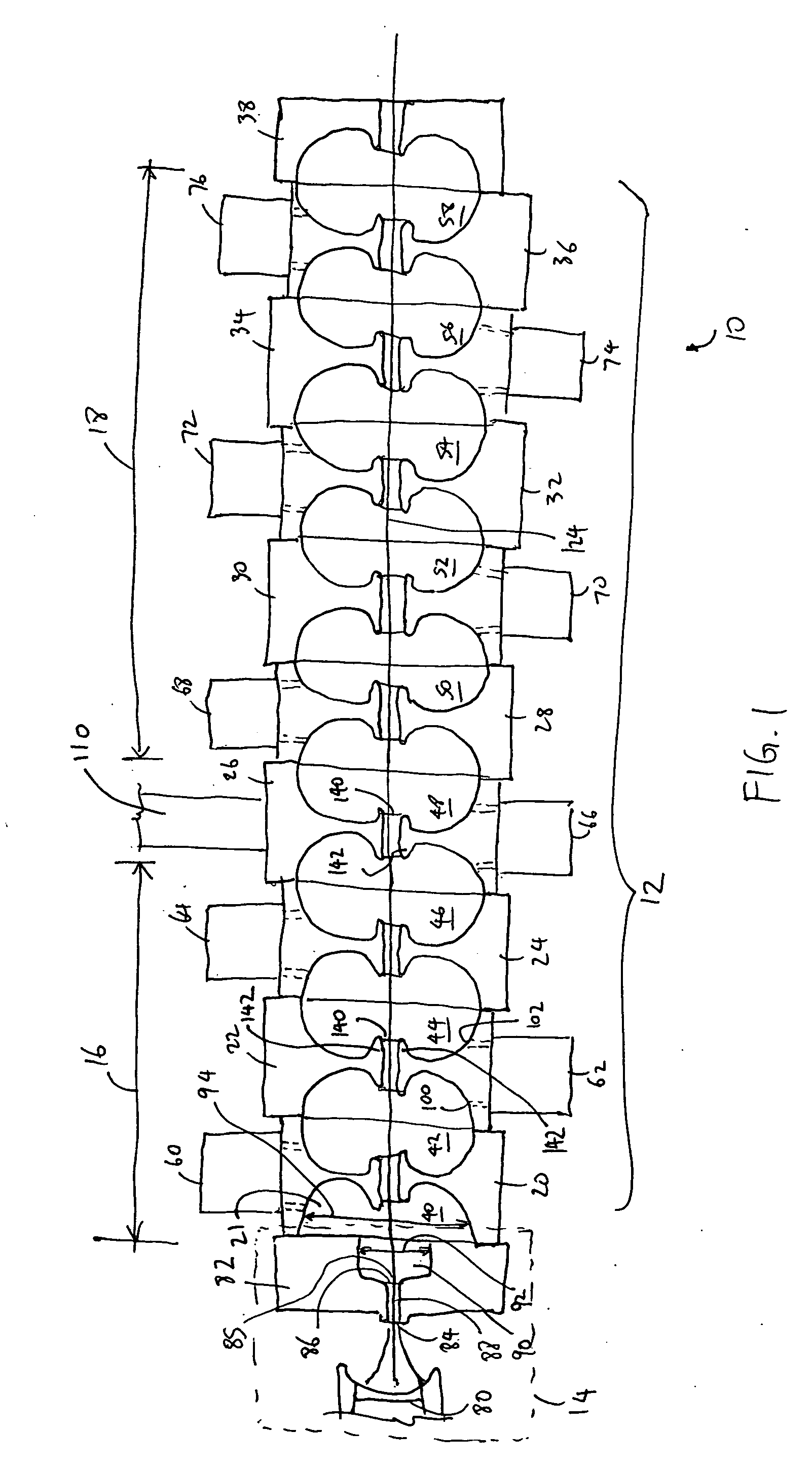
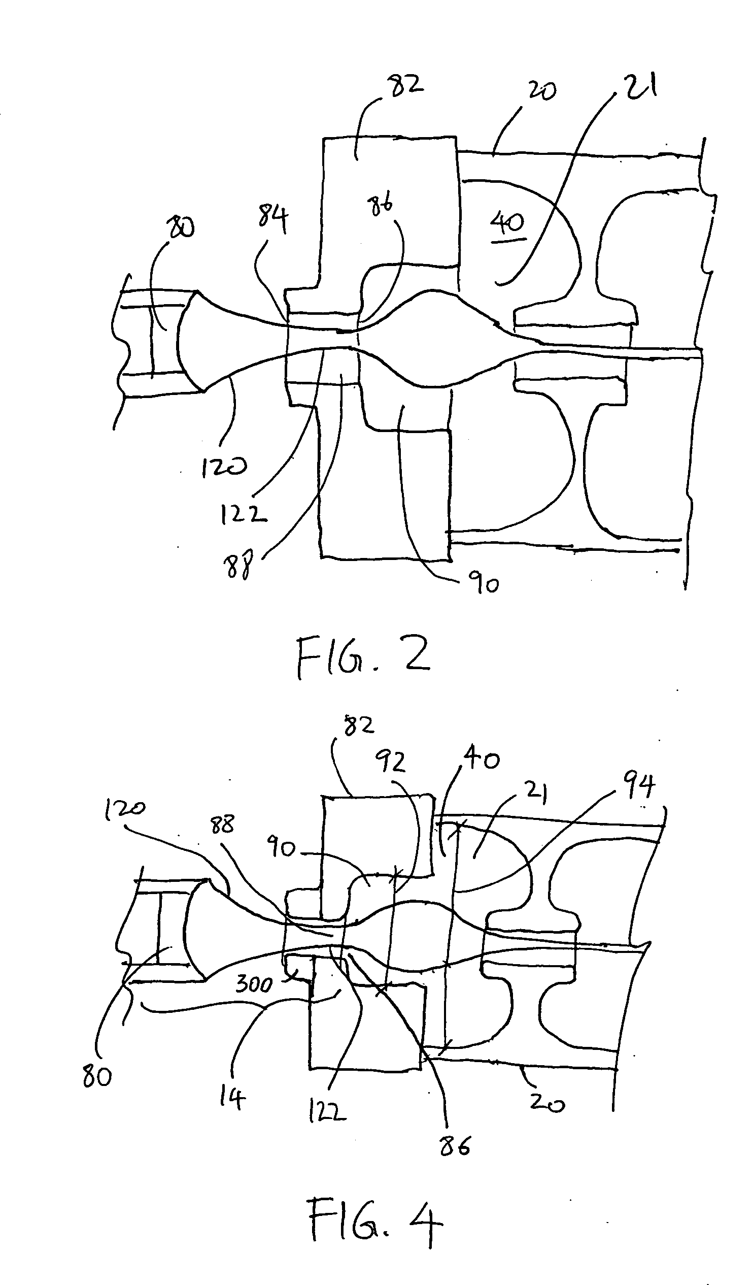
[0035] A standing wave electron beam accelerator employing (1) waist position optimization (2) asymmetric stepped structure, and (3) cell length variation along the length of the accelerator, has been built. The accelerator includes a low voltage electron source that operates at 30 keV (or less), and a microwave source. In one mode of operation, the accelerator delivers a beam of electrons having an energy level of 9 MeV±0.5 MeV with at least 30% transmission (at least 30% of the electrons generated at a proximal end of the accelerator is transmitted to a distal end). In another mode of operation, the accelerator delivers a beam of electrons having an energy level of 5 MeV±0.5 MeV. By configuring the asymmetric stepped structure to place the waist of the electron envelope at optimal position, and by configuring the electromagnetic cavities to provide desired phase focusing effect, the electrons traveling though the accelerator can be efficiently bunched without use of an external so...


PUM


Abstract

A method for generating an electron beam includes prescribing a location, and generating an envelope of electrons, the envelope having a waist, wherein the generating is performed such that the waist of the envelope is at or adjacent to the prescribed location. A device for generating an electron beam includes a gun source for generating electrons, and a plurality of electromagnetic cavities coupled in series to form a body, the electromagnetic cavities configured to accelerate at least some of the electrons to create a beam of electrons at an energy level having a value between 5 MeV and 20 MeV, the beam of electrons having a cross sectional dimension that is 0.02 λ (or 2 mm) or less.

Description

RELATED APPLICATION DATA [0001] This application is a continuation-in-part of U.S. patent application Ser. No. 10 / 407,101, filed on Apr. 3, 2003, the entire disclosure of which is expressly incorporated by reference herein.BACKGROUND OF THE INVENTION [0002] 1. Field of the Invention [0003] This invention relates generally to standing wave electron beam accelerators, and more particularly, to electron accelerators for generating x-ray and electron beams of different energies. [0004] 2. Background of the Invention [0005] Standing wave electron beam accelerators have found wide usage in medical accelerators where the high energy electron beam is employed to generate x-rays for therapeutic and diagnostic purposes. Electron beam generated by an electron beam accelerator can also be used directly or indirectly to kill infectious pests, to sterilize objects, to change physical properties of objects, and to perform testing and inspection of objects, such as radioactive containers and concre...

Claims


Application Information

Patent Timeline
Patent Type & Authority Applications(United States)
IPC IPC(8): H01J35/00H05H9/04
CPCH05H9/04H01J35/00
Inventor SALOP, ARTHURWHITTUM, DAVID H.KAUFFMAN, MICHAEL A.TRAIL, MARK E.MEDDAUGH, GARD E.
Owner VARIAN MEDICAL SYSTEMS
Why Eureka
Try Eureka