Self-limiting pulse width modulation regulator

a regulator and pulse width technology, applied in the direction of pulse technique, generating/distributing signals, instruments, etc., can solve the problems of compromising the performance and reliability of the regulator, continuing to fall, and undershooting conditions, and achieve the effect of minimizing undershoot and overshoot conditions

Inactive Publication Date: 2005-06-23
ATMEL CORP
View PDF31 Cites 1 Cited by
  • Summary
  • Abstract
  • Description
  • Claims
  • Application Information

AI Technical Summary

Benefits of technology

[0009] A self-adjusting PWM regulator which minimizes undershoot and overshoot conditions is disclosed. The regulator includes a charge pump, a voltage comparator circuit, and a latch circuit. The input of the voltage comparator circuit includes an output of the charge pump. The input of the latch circuit includes an output from the voltage comparator circuit. The latch circuit includes a pair of SR latches coupled to a pair of AND / OR gates. The latch circuit transmits a first signal to the charge pump to prevent an overshoot condition if the output from the voltage comparator circuit is in a first state, and transmits a second signal to prevent an undershoot condition if the output from the voltage comparator circuit is in a second state. This keeps the charge pump adjusted within the limits of its control. Also, the latch circuit keeps the regulator automatically adjusted to changes in voltage, temperature, frequency or processing of the regulator.

Problems solved by technology

However, the voltage on node pgate (130) can continue to fall, creating an undershoot condition.
Both overshoot and undershoot conditions compromise the performance and reliability of the regulator (10).

Method used


Image

  • Self-limiting pulse width modulation regulator
  • Self-limiting pulse width modulation regulator
  • Self-limiting pulse width modulation regulator

Examples


Embodiment Construction

[0017] The present invention provides a Pulse Width Modulation (PWM) regulator which minimizes undershoot and overshoot conditions. The following description is presented to enable one of ordinary skill in the art to make and use the invention and is provided in the context of a patent application and its requirements. Various modifications to the preferred embodiment will be readily apparent to those skilled in the art and the generic principles herein may be applied to other embodiments. Thus, the present invention is not intended to be limited to the embodiment shown but is to be accorded the widest scope consistent with the principles and features described herein.

[0018] To more particularly describe the features of the present invention, please refer to FIGS. 3 through 8 in conjunction with the discussion below.

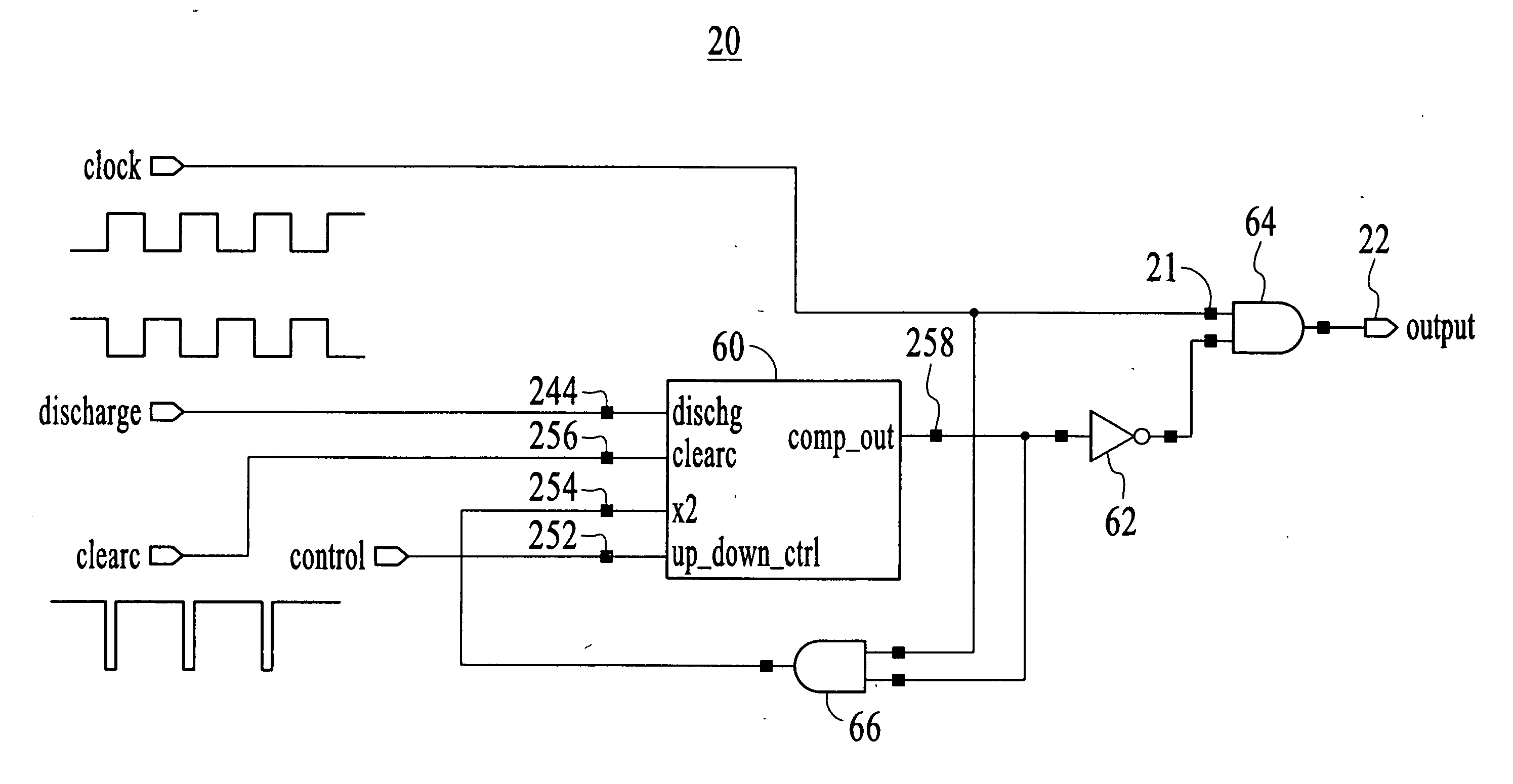
[0019]FIG. 3 illustrates an embodiment of the PWM regulator in accordance with the present invention. The regulator (20) comprises a variable delay generator (60), an ...


PUM


Abstract

A self-adjusting PWM regulator which minimizes undershoot and overshoot conditions is disclosed. The regulator includes a charge pump, a voltage comparator circuit, and a latch circuit. The input of the voltage comparator circuit includes an output of the charge pump. The input of the latch circuit includes an output from the voltage comparator circuit. The latch circuit includes a pair of SR latches coupled to a pair of AND / OR gates. The latch circuit transmits a first signal to the charge pump to prevent an overshoot condition if the output from the voltage comparator circuit is in a first state, and transmits a second signal to prevent an undershoot condition if the output from the voltage comparator circuit is in a second state. This keeps the charge pump adjusted within the limits of its control.

Description

FIELD OF THE INVENTION [0001] The present invention relates to pulse width modulation regulators, and more particularly to the minimizing of undershoot and overshoot conditions in pulse width modulation regulators. BACKGROUND OF THE INVENTION [0002]FIG. 1 illustrates a conventional pulse width modulation (PWM) regulator. The regulator (10) comprises a variable delay generator (40), an inverter (42), and an AND gate (44). The variable delay generator (40) received a dischg signal (I 38) and an up_down_ctrl signal (132), as input, and outputs a comp_out signal (136). The AND gate (44) receives a clock signal (11) and an inverted comp_out signal as inputs. [0003] Assuming a 50-50 duty clock cycle, the comp_out signal (136) is low at the beginning of the cycle. When the clock signal (11) goes high, the output (12) goes high. Once the comp_out signal (136) goes high, the AND gate (44) brings the output (12) low. Thus, the width of the high pulse is controlled by the delay between the clo...

Claims


Application Information

Patent Timeline
Patent Type & Authority Applications(United States)
IPC IPC(8): H03K3/017H03K3/0231H03K5/08H03K7/08
CPCH03K3/017H03K7/08H03K5/082H03K3/0231
Inventor WEINER, ALBERT S.
Owner ATMEL CORP
Why Eureka
Try Eureka