
Method and system for adaptive bit depth enhancement for displays

a display and bit depth technology, applied in the field of visual displays, can solve the problems of exacerbated problem of inadequate bit resolution, often possessing inadequate bit depth resolution for high-resolution displays, and achieving the effects of reducing false contours, smoothing out background splotches, and improving quality

Active Publication Date: 2005-06-23
TEXAS INSTR INC
View PDF4 Cites 12 Cited by
  • Summary
  • Abstract
  • Description
  • Claims
  • Application Information

AI Technical Summary

Benefits of technology

[0006] Some embodiments of the invention provide numerous technical advantages. Some embodiments may benefit from some, none, or all of these advantages. For example, in one embodiment of the invention, false contours may be mitigated and background splotchiness smoothed out through the use of a relatively inexpensive filter. Thus, better quality images may be displayed without the use of more expensive and sophisticated front end decoders. Further, by avoiding the use of more sophisticated and expensive front end decoders, fewer input pins are required to manage the increased input resolution. Thus, image contouring may be addressed without replacing integrated circuits or impacting input / output operations of application specific integrated circuits by instead addressing the contouring problem through signal processing.

Problems solved by technology

For cost reasons, such decoders often possess inadequate resolution for high resolution displays.
This problem of inadequate bit resolution is exacerbated by other processing steps used in digital light processing systems.
Other processing steps further exacerbate the problem of inadequate bit resolution.
This increase in DMDTM precision and projector contrast further exacerbates contours resulting in inadequate input bit precision.

Method used


Image

  • Method and system for adaptive bit depth enhancement for displays
  • Method and system for adaptive bit depth enhancement for displays
  • Method and system for adaptive bit depth enhancement for displays

Examples


Embodiment Construction

[0019] Embodiments of the invention and its advantages are best understood by referring to FIGS. 1 through 5C of the drawings, like numerals being used for like and corresponding parts of the various drawings.

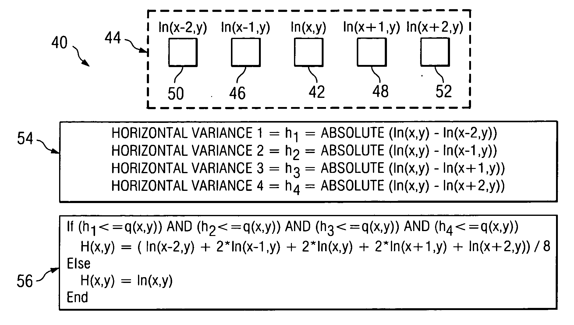
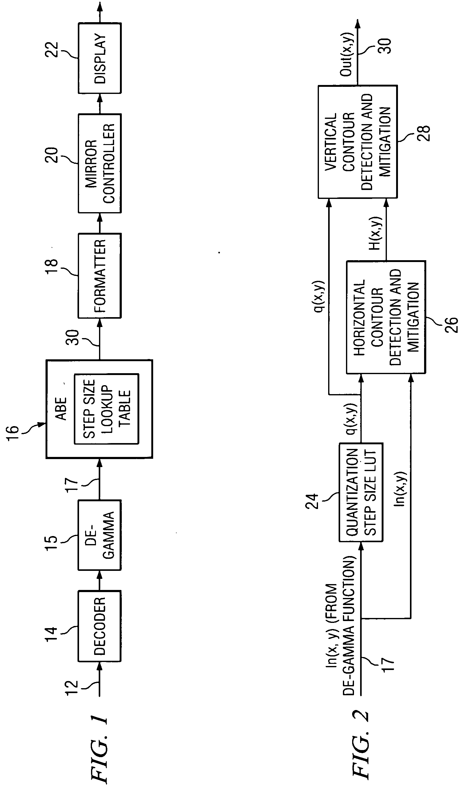
[0020]FIG. 1 is a block diagram of a light processing system 10 according to the teachings of the invention. System 10 receives a data source 12, such as a television feed. Source 12 may be received by a decoder 14, which decodes the analog source signal and generates a plurality of digital bits. Conventionally a plurality of bits are utilized to represent a value corresponding to an intensity level for a particular pixel to be displayed. As described above, decoders 14 may be of insufficient precision for high resolution displays, particularly in Digital Light Processing (DLP) systems, which utilize a linear display as opposed to the non-linear display of conventional CRTs. Because of the linear display in DLP systems, a de-gamma function is applied to the decoded data receiv...


PUM


Abstract

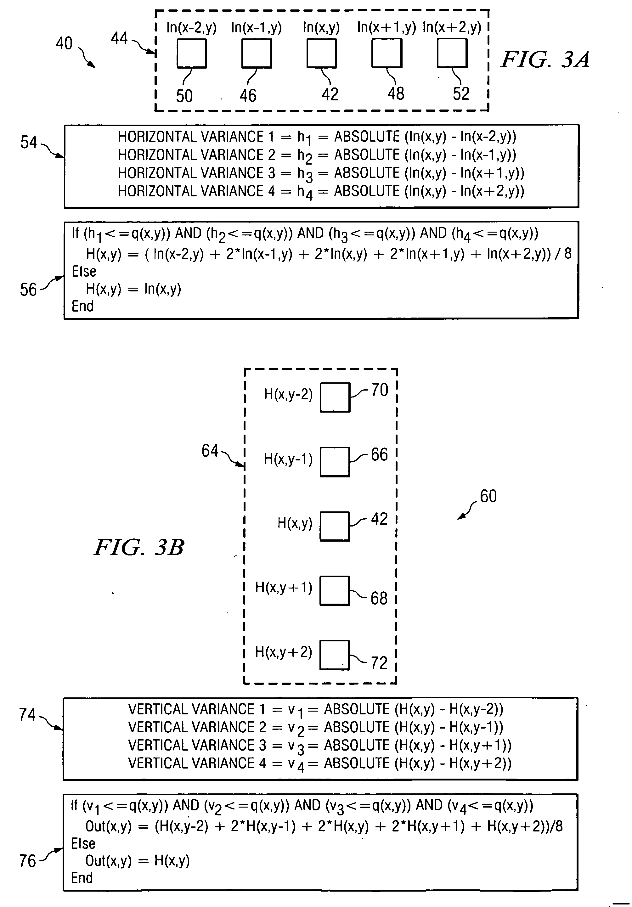
According to one embodiment, a method for compensating for inadequate bit resolution in a light processing system includes receiving a plurality of values each indicative of an intensity level for a pixel to be displayed. Each of the values is represented by a plurality of bits of data. The method also includes determining a quantization step size for the plurality of bits of data. For at least one particular pixel of the pixels, a set of consecutive pixels including the particular pixel is selected. The method also includes determining a difference between the value associated with the particular pixel in the set and each value associated with the other pixels in the set, and also determining that all of the determined differences are less than or equal to the quantization step size. In response, a filtered value for the particular pixel in the set is generated based at least on some of the pixels in the set in addition to the particular pixel.

Description

TECHNICAL FIELD OF THE INVENTION [0001] This invention relates generally to visual displays and more particularly to a method and system for adaptive bit depth enhancement for displays. BACKGROUND OF THE INVENTION [0002] Television displays and other types of displays often receive a data stream that is decoded by a decoder. For cost reasons, such decoders often possess inadequate resolution for high resolution displays. For example, eight bit decoders may be utilized where twelve or fourteen bit decoders would be more desirable. [0003] This problem of inadequate bit resolution is exacerbated by other processing steps used in digital light processing systems. For example, to account for the non-linear response of a cathode ray tube, television signal images traditionally have a non-linear transfer function applied, and the non-linear response is provided as the input signal. This non-linear function is referred to as a gamma correction curve. In linear devices such as Digital Light ...

Claims


Application Information

Patent Timeline
IPC IPC(8): G09G3/20G09G3/34G09G5/10
CPCG09G3/2007G09G2320/062G09G2320/0271G09G3/346
Inventor KEMPF, JEFFREY M.
Owner TEXAS INSTR INC
Learn More