Alignment mechanism for direct marking printheads and a method for aligning printheads in a printer

a technology of printing and alignment mechanism, which is applied in the direction of power drive mechanism, printing, instruments, etc., can solve the problems of poor manufacturing tolerance, inconvenient, and misalignment of printheads, so as to reduce the vibration of the printhead, reduce the thermal expansion of the printhead, and increase the life of the printer

Active Publication Date: 2005-06-23
XEROX CORP
View PDF3 Cites 68 Cited by
  • Summary
  • Abstract
  • Description
  • Claims
  • Application Information

AI Technical Summary

Benefits of technology

[0008] There is a need for an alignment mechanism for printheads in all six degrees of freedom or less, with sufficient accuracy to allow high image quality.
[0015] In exemplary embodiments, the thermal expansion of the printhead may be reduced by minimizing the number of required alignment mechanisms for a multiple staggered printhead assembly for a printer.
[0016] In exemplary embodiments, the vibration of the printhead may be reduced by a more compact alignment mechanism that may be more centrally located with respect to the printhead.
[0017] In exemplary embodiments, increased life of the printer can be achieved by the reduction in vibration and thermal expansion of the different parts of the printer.

Problems solved by technology

Misalignment of printheads may be due to, for example, poor manufacturing tolerances, thermal expansion of the printhead and associated parts of the printer, vibration of the printhead, or the like.
This is not suitable since misalignment may occur in any of the six degrees of freedom (translation and rotation).
However, this leads to a larger footprint area of the alignment mechanisms, more parts, and thus more thermal expansion and vibration, further leading to misalignment of the printhead.

Method used


Image

  • Alignment mechanism for direct marking printheads and a method for aligning printheads in a printer
  • Alignment mechanism for direct marking printheads and a method for aligning printheads in a printer
  • Alignment mechanism for direct marking printheads and a method for aligning printheads in a printer

Examples


Embodiment Construction

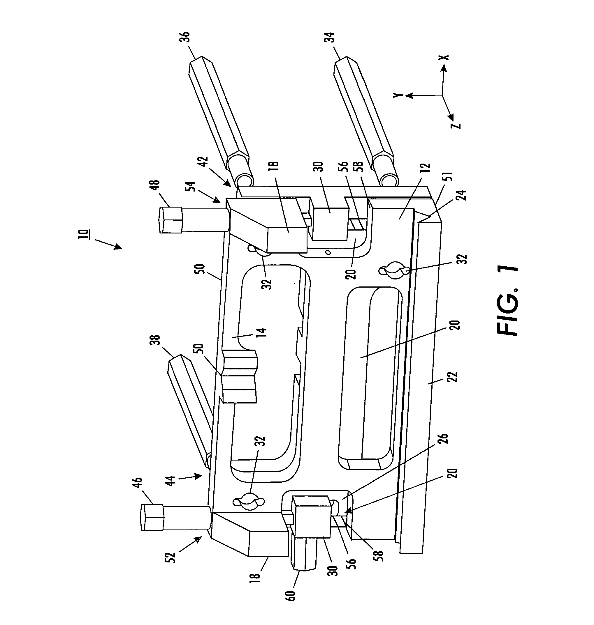
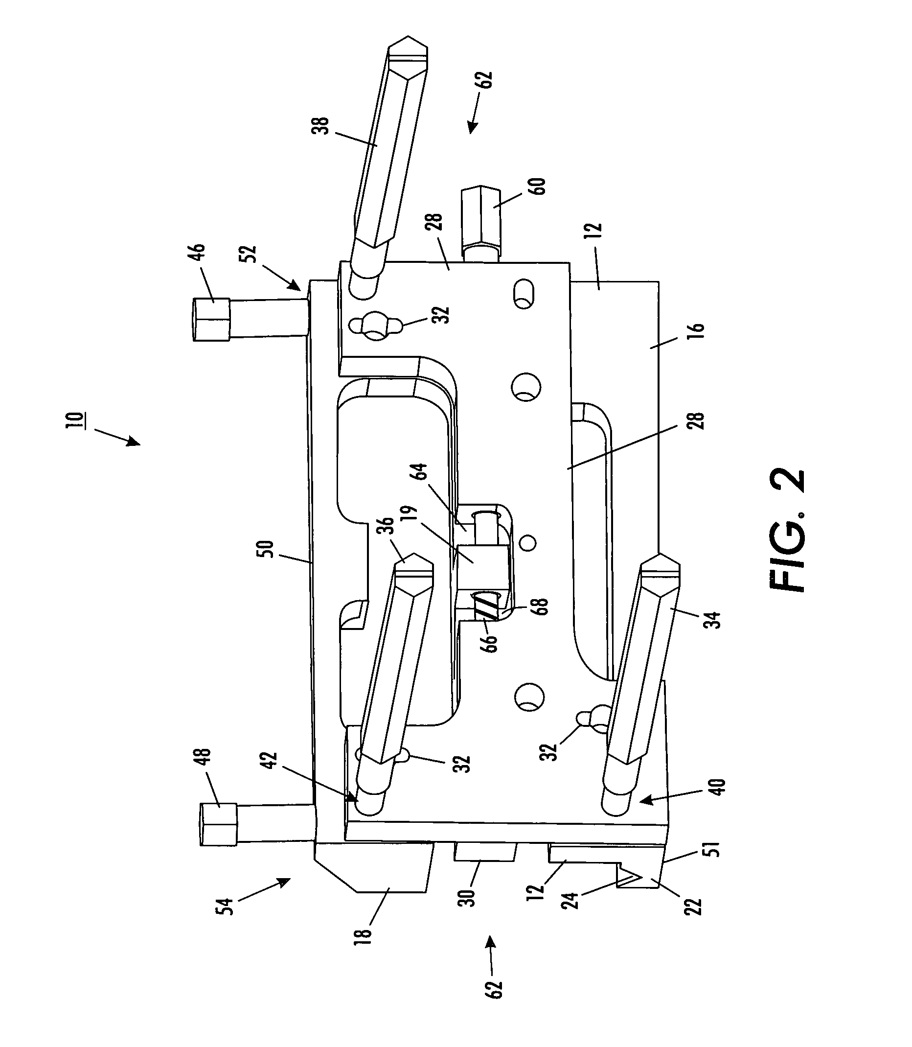
[0026] Six degrees of freedom, as used herein, refers to each of the degrees of translation and rotation with respect to the X, Y, and Z axes. That is, the six degrees of freedom comprise (1) translation in the X direction, (2) translation in the Y direction, (3) translation in the Z direction, (4) rotation about the X axis, (5) rotation about the Y axis and (6) rotation about the Z axis.

[0027] Referring to FIGS. 1 and 2, an alignment mechanism 10 of the present invention is illustrated. The alignment mechanism contains a plate 12 having a front surface 14 and a back surface 16. A plurality of protrusions 18 are located on the front surface 14 of the plate 12. Two of the plurality of protrusions 18 are each located on opposite sides of the plate 12 and extend from the front surface 14 of the plate 12. Openings 20 in the plate 12 are located at least under each of the two protrusions 18. The openings 20 allow for a reduced total mass of the alignment mechanism and may be designed to...


PUM


Abstract

A device and method for the alignment, in upto six degrees of freedom, of printheads in a printer is disclosed. The device has a support, wherein the printhead is secured to a substantially center location of the support. The device further has a fixed plate biased against the support by a plurality of first screws extending substantially in a Z direction, a plurality of second screws extending substantially in a Y direction, and a third screw extending substantially in an X direction. The fixed plate, and thus the print head, may be translated in each of the X, Y and Z directions and may be rotated about each of the X, Y, and Z axes by manipulation of the screws to achieve possible alignment in all six degrees of freedom.

Description

BACKGROUND OF THE INVENTION [0001] 1. Field of Invention [0002] This invention is directed to direct marking systems that utilize multiple staggered printheads in order to achieve full width printing per pass. More specifically, this invention is directed to a device and method for the alignment, in six degrees of freedom or less, of multiple printheads in a printer by providing adjustments in upto all six degrees of freedom for each printhead. [0003] 2. Description of Related Art [0004] Misalignment of printheads may be due to, for example, poor manufacturing tolerances, thermal expansion of the printhead and associated parts of the printer, vibration of the printhead, or the like. Thus, aligning the printheads with sufficient accuracy to allow high image quality is desired. [0005] Devices for alignment of printheads in a printer are known. For example, U.S. Pat. No. 6,068,415 to Smolenski discloses a printhead that is spring loaded, permitting it to float in both the vertical and ...

Claims


Application Information

Patent Timeline
Patent Type & Authority Applications(United States)
IPC IPC(8): B41J2/21B41J25/304B41J25/312B41J25/316
CPCB41J25/304B41J2/2135
Inventor WILLIAMS, ANTONIO L.GEORGE, CLIFFORD L.
Owner XEROX CORP
Why Eureka
Try Eureka