Replacement apparatus for an optical element

a technology of replacement apparatus and optical element, which is applied in the direction of photomechanical apparatus, instruments, nuclear engineering, etc., can solve the problems that the known procedures and the apparatus for replacing the last optical element are not suitable for this purpose, and achieve the effect of improving the image performance of the lithography objectiv

Active Publication Date: 2005-06-23
CARL ZEISS SMT GMBH
View PDF99 Cites 26 Cited by
  • Summary
  • Abstract
  • Description
  • Claims
  • Application Information

AI Technical Summary

Benefits of technology

[0010] This replacement apparatus is capable of removing the optical element from the lithography objective and of moving another optical element, matched specifically to the changes within the lithography objective, into the lithography objective again. By these means, the imaging performance of the lithography objective can be improved considerably without any intervention in the structure of the lithography objective. All that is necessary is a lateral opening in the housing of the lithography objective, which is dimensioned such that the holder can move into the housing. In this case, the holder is capable of positioning the optical element very accurately within the lithography objective.

Problems solved by technology

The known procedures and apparatus for replacing the last optical element are not suitable for this purpose, however.

Method used


Image

  • Replacement apparatus for an optical element
  • Replacement apparatus for an optical element
  • Replacement apparatus for an optical element

Examples


second embodiment

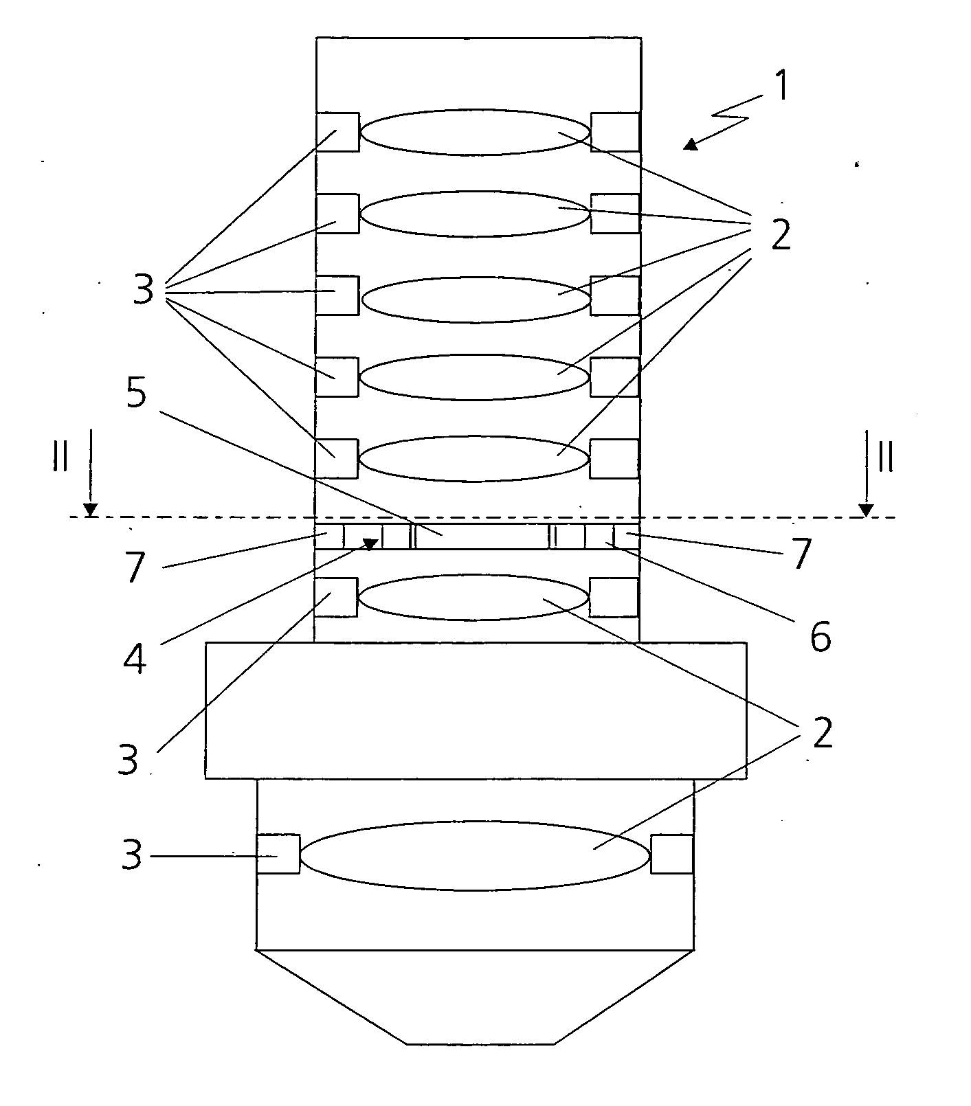
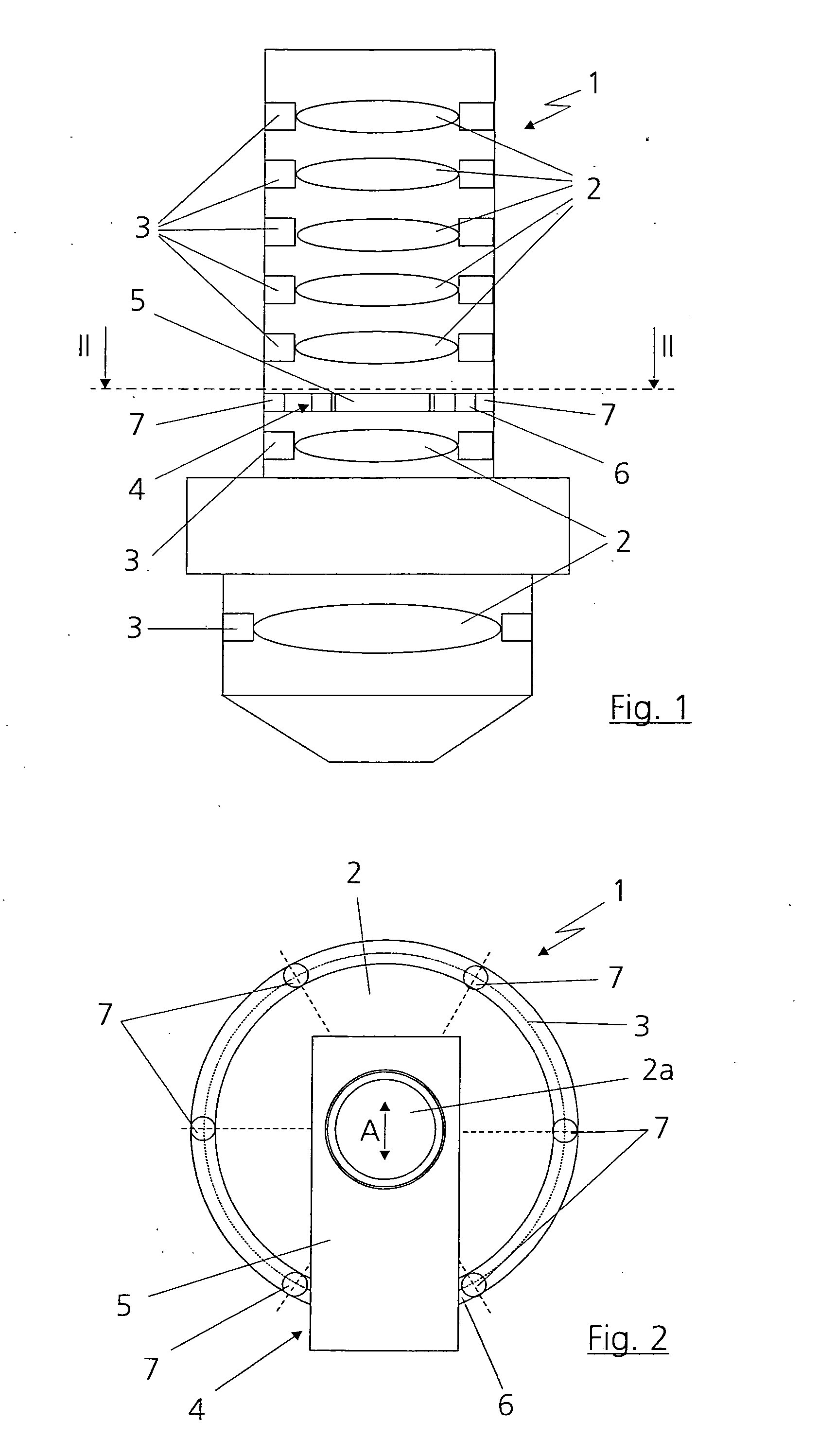
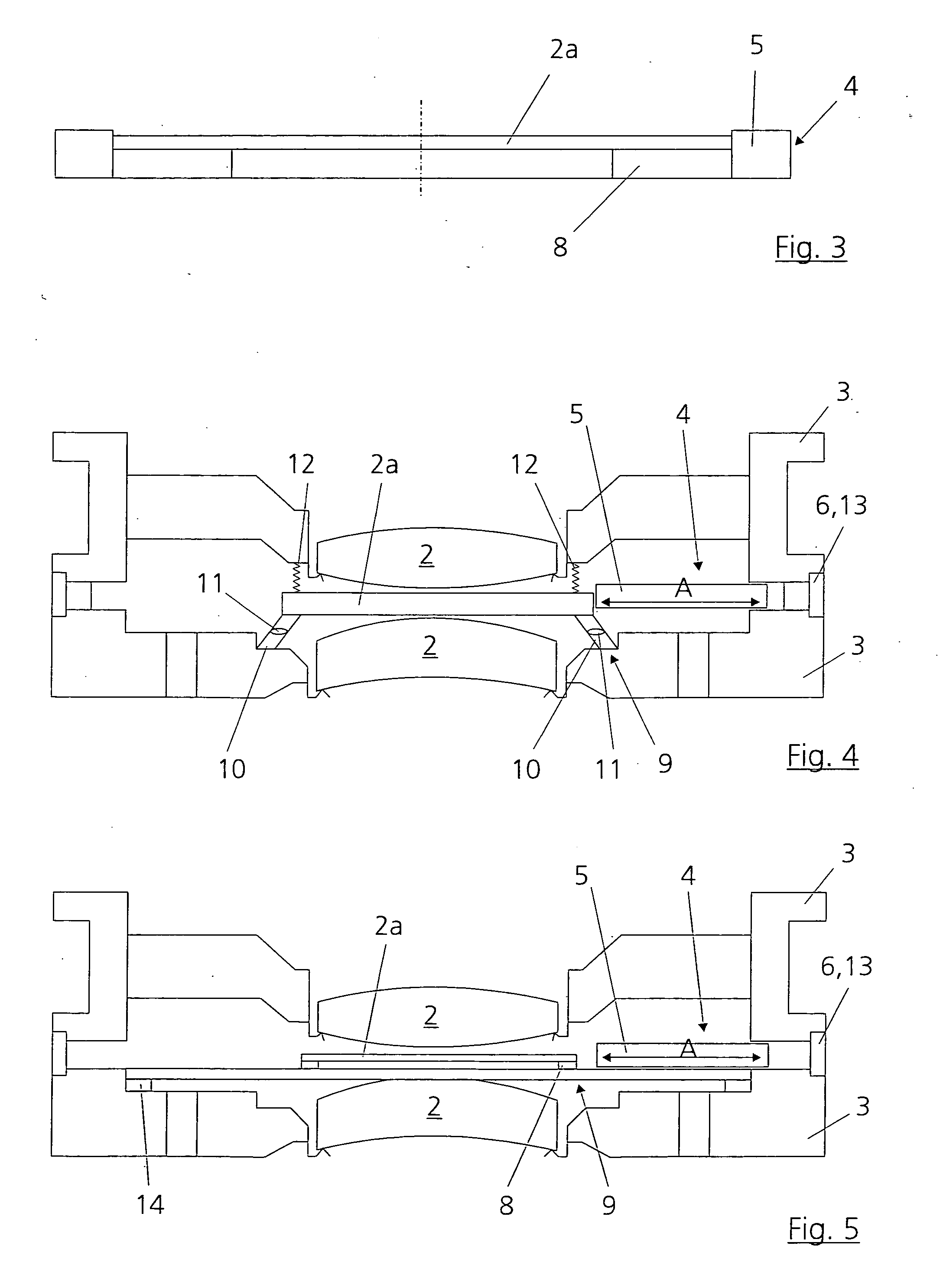
[0030] the replacement apparatus 4 is illustrated in FIG. 4. Once again, the replaceable optical element 2a is arranged between two optical elements 2 mounted in the lithography objective 1 by means of respective mounts 3. In order to hold and to mount the optical element 2a within the lithography objective 1, use is made of a separate holding structure 9 which, in this case, is placed on mount 3 of the adjacent optical element 2a, which is located underneath the replaceable optical element 2a. Although this is not illustrated, the optical element 2a could also be provided with the stiffening element 8 in this case. The separate holding structure 9 preferably has three supports 10, of which only two can be seen in the illustration according to FIG. 4. To this extent, this is an isostatic mounting of the optical element 2a within the lithography objective 1. In addition, the separate holding structure 9 has a plurality of actuators 11, which are capable of aligning the optical elemen...

first embodiment

[0036] the seal 13 for sealing the opening 6 of the housing 1a is illustrated in FIG. 7. In this case, a cover plate 17 is provided, which is sealed with respect to the housing 1a via an O-ring 18. In this way, contamination of the interior of the housing 1a of the lithography objective 1 is prevented, at the same time the accessibility of the opening 6 being ensured. Instead of the solid material seal, an elastic gasket or a metal seal or a Viton seal can also be used. If a metal seal is used, its material can for example be copper.

[0037] The embodiment of the seal 13 according to FIG. 8 is a gas seal or a gas-dynamic restrictor, which is based on the principle that, by means of the pressure pi within the housing 1a of the lithography objective 1, which is increased by comparison with the pressure pa outside the housing 1a, no gaseous substances or other contaminants can penetrate into the housing 1a. For this purpose, the cover plate 17 is again provided to be fastened opposite th...


PUM

PropertyMeasurementUnit
widthaaaaaaaaaa
microstructuredaaaaaaaaaa
imaging performanceaaaaaaaaaa

Abstract

A replacement apparatus for an optical element mounted between two adjacent optical elements in a lithography objective has a holder for the optical element to be replaced, which holder can be moved into the lithography objective through a lateral opening in a housing of the same.

Description

BACKGROUND OF THE INVENTION [0001] 1. Field of the Invention [0002] The invention relates to a replacement apparatus for an optical element arranged between two adjacent optical elements in a lithography objective. Furthermore, the invention relates to a lithography objective. [0003] 2. Description of the Prior Art [0004] Lithography objectives are known in which the last optical element, that is to say the one located closest to the wafer to be exposed, is replaceable. [0005] Furthermore, projection objectives exist in which lens barrels are held in a support structure and can be replaced in their entirety. In order to make this possible, it is necessary to break down the entire structure of the objective. [0006] With regard to the prior art relating to the invention, reference is made to the documents U.S. 2002 / 0167740 A1 and U.S. Pat. No. 6,449,106 B1. [0007] If the optical elements within a lithography objective, such as lenses or mirrors, for example, change over the course of ...

Claims


Application Information

Patent Timeline
Patent Type & Authority Applications(United States)
IPC IPC(8): G02B7/00G02B7/02G02B7/14G02B13/14G03F7/20
CPCG02B7/00G02B7/02G02B7/14G03F7/7015G03F7/70258G03F7/70825G02B7/023G02B13/14G03F7/70191
Inventor KUGLER, JENSSORG, FRANZWURMBRAND, ANDREASSCHLETTERER, THOMASITTNER, THOMAS
Owner CARL ZEISS SMT GMBH
Why Eureka
Try Eureka