Projection objective and method for its manufacture

a technology of projection objective and manufacturing method, which is applied in the direction of photomechanical equipment, instruments, nuclear engineering, etc., can solve the problems of high demands on the reproduction properties of projection objective, insufficiently transparent materials available for lens manufacturing, and insufficiently accurate correction of projection objective, etc., to reduce manufacturing-related aberrations

Inactive Publication Date: 2005-06-23
CARL ZEISS SMT GMBH
View PDF10 Cites 49 Cited by
  • Summary
  • Abstract
  • Description
  • Claims
  • Application Information

AI Technical Summary

Benefits of technology

[0014] It is a further object of the present invention to provide an improved method of manufacturing EUV projection obj...

Problems solved by technology

When using projection light with such short wavelengths, no sufficiently transparent materials are available for manufacturing lenses and other refractive optical elements.
Due to the small size of the structures to be reproduced, high demands are made on the reproduction properties of the projection objective.
On the one hand there are aberrations which result from the design of the projection objective, i.e. from the specification of the dimensions, materials and distances of the optical elements contained in the projection objective.
On the other hand there are aberrations that are due to manufacturing or material defects and...

Method used


Image

  • Projection objective and method for its manufacture
  • Projection objective and method for its manufacture
  • Projection objective and method for its manufacture

Examples


Embodiment Construction

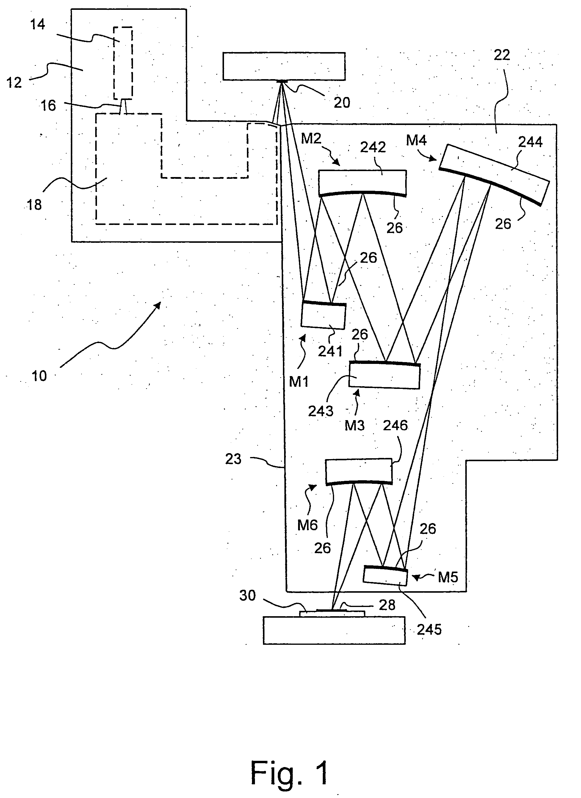
[0048] In FIG. 1 a microlithographic projection exposure apparatus is illustrated in a very schematized and not to-scale meridian section and designated in its entirety by the reference numeral 10. The projection exposure apparatus 10 comprises an illumination system 12, in Which a light source 14 is arranged. The light source 14 serves to generate projection light, Which is indicated by 16 and has a wavelength in the extreme ultraviolet spectral range, for example 13.5 nm In addition, illumination optics only indicated by 18 are part of the illuminations system 12 that allow to direct the projection light 16 onto a reticle 20. The illumination device 12 is known as such in the prior art, for example from EP 1 123 1 95 A1, and is therefore not described here in more detail.

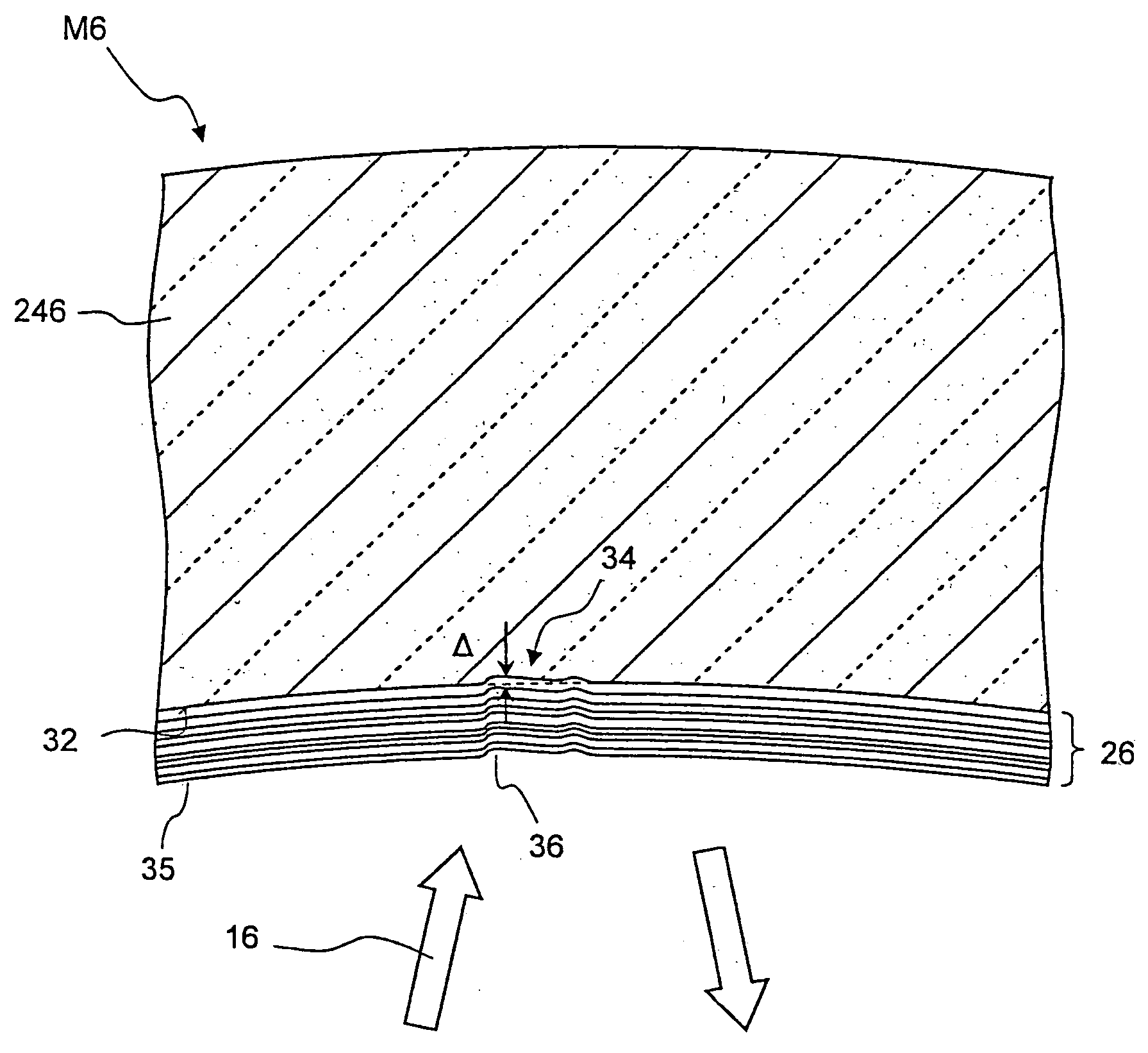
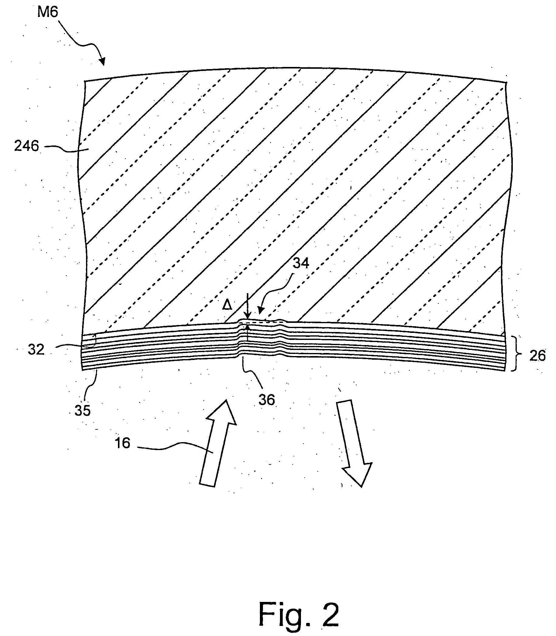
[0049] The projection light 16 reflected by the reticle 20 enters a projection objective 22, which in the embodiment illustrated, contains 6 aspheric projecting mirrors M1, M2, . . . , M6 arranged in a housing 23...


PUM


Abstract

A method of manufacturing a projection objective (22) of a microlithographic projection exposure apparatus (10) is described. The projection objective (22) comprises at least one mirror (M1 to M6) that each have a mirror support (241 to 246) and a reflective coating (26) applied thereon. First imaging aberrations of a pre-assembled projection objective are measured. Before the coating (26) is applied, the mirror supports (241 to 246) are provided with a desired surface deformation (34). If the mirrors (M1 to M6) are not reflective for projection light without the coating (26), measuring light is used that has another wavelength. Alternatively, two identical mirror supports (246) may be provided. One support having a reflective coating is part of the pre-assembled projection objective whose imaging aberrations are measured. The other support is provided with surface deformations before coating and mounting the support into the objective.

Description

BACKGROUND OF THE INVENTION [0001] 1. Field of the Invention [0002] The invention quite generally relates to projection objectives of microlithographic projection exposure apparatus, which have at least one mirror with a mirror carrier and a reflective coating applied thereon. In particular, the invention relates to EUV projection objectives that use projection light with a wavelength in the extreme ultraviolet spectral range (EUV). [0003] 2. Description of Related Art [0004] Microlithographic projection exposure apparatus, as used for manufacturing integrated electrical circuits and other micro-structured components, reproduce structures, which are contained in a reticle, generally reduced on a photo-sensitive layer that can be applied on a silicon wafer for example. [0005] One of the main aims in the development of projection exposure apparatus consists of being able to lithographically define structures with increasingly smaller dimensions on the photo-sensitive layer. The produc...

Claims


Application Information

Patent Timeline
IPC IPC(8): G02B1/10G02B5/08G02B17/06G03F7/20
CPCG02B5/0891G02B17/0663Y10S359/90G03F7/70958G21K2201/067G03F7/706
Inventor MANN, HANS-JUERGENMUELLENDER, STEPHANTRENKLER, JOHANNENKISCH, HARTMUT
Owner CARL ZEISS SMT GMBH
Why Eureka
Try Eureka