Ring binder mechanism with pronged metal anchors

a technology of metal anchors and ring binder, which is applied in the field of ring binder mechanism with pronged metal anchors, can solve the problems of not always providing enough retention force for anchors, rivet heads that are visible on closed binders, and resistance to labeling sheets, so as to minimize the force needed, enhance the appearance of the binder, and avoid the effect of title sheet insertion resistan

Inactive Publication Date: 2005-06-23
HONG KONG STATIONERY MFG
View PDF24 Cites 0 Cited by
  • Summary
  • Abstract
  • Description
  • Claims
  • Application Information

AI Technical Summary

Benefits of technology

[0006] The primary objective of the invention is to hide the rivet head and to simplify the process of securing the ring mechanism to a typical binder.
[0007] A related goal is to construct an anchor that can penetrate the chipboard of the binder when the eyelets are pressed towards the chipboard, while minimizing the required pressing force.
[0010] Since, with this invention, the prongs are submerged in the chipboard, no additional rivet is needed to fix the ring mechanism with the pronged anchor to the chipboard. And because neither a rivet head nor a pronged metal anchor shows from the outside of a closed binder, the appearance of the binder is enhanced, and there is no resistance to insertion of the title sheet when using a clear vinyl overlay binder.
[0011] The present construction minimizes the force needed to secure the ring mechanism to the binder and maximizes the force required to detach it. The force required to secure the ring mechanism affects to the cost of the manufacturing process; the force required to remove the ring mechanism from the binder determines the security of the loose leaf papers holding in the binder.

Problems solved by technology

It is unpleasant to see exposed rivet heads on a closed binder.
Moreover, if the ring mechanism is riveted to a clear vinyl overlay binder, the rivet heads usually cause resistance to the labeling sheet when it is inserted into the clear vinyl pocket.
But these anchors do not always provide enough retention force, even though they may be pressed against the spine with a large application force.

Method used


Image

  • Ring binder mechanism with pronged metal anchors
  • Ring binder mechanism with pronged metal anchors
  • Ring binder mechanism with pronged metal anchors

Examples


Embodiment Construction

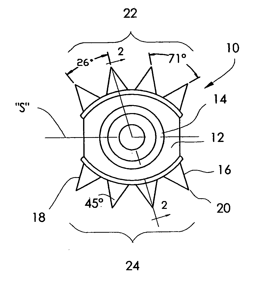
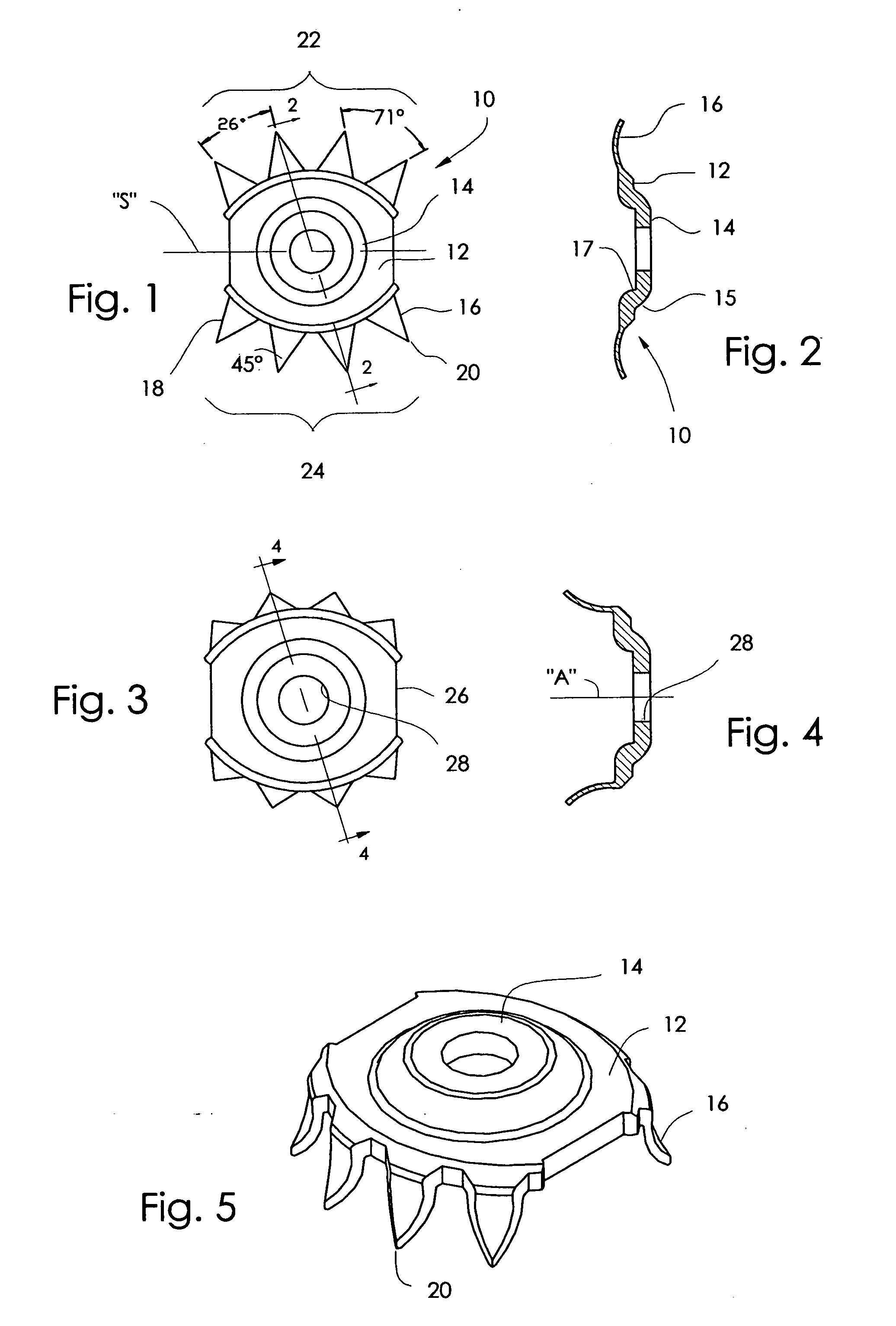
[0023] According to this invention, a pronged anchor 10 is formed by stamping a small metal plate into the shape shown in FIG. 1. The pronged plate has an annular outer portion 12, a raised central portion 14 defined by a circular step 15, and a plurality of prongs 16 extending outward from the outer portion. The step also defines a shallow recess 17 on the bottom of the plate. Note (FIG. 2) that the prongs are substantially thinner—actually, less than half as thick as—the rest of the plate.

[0024] Each of the prongs has lateral sides 18 which subtend an angle 45° (FIG. 1) with each other and meet at the prong's tip 20. The included angle between the sides of adjacent prongs is about 71°. The prongs are arranged in two sets 22, 24 which extend in opposite directions from a plane of symmetry “S”. Within each set, the prongs diverge, having equiangular spacing of about 26° (FIG. 1) about respective centers which lie beyond the center of the hole. The prongs do not extend 360° around t...


PUM


Abstract

A ring binder mechanism is attached to the spine of a notebook by pressing prongs of pre-attached anchors into the spine material. The prongs are curved outward slightly, and are thinner than the centers of the anchors, so that they spread outward as force is applied to the anchors. The prongs are arranged in two sets which face in opposite directions. Anchors so constructed provide good retention force while requiring a minimum application force, and cannot be seen from outside the binder.

Description

BACKGROUND OF THE INVENTION [0001] This invention relates to a ring binder mechanism having pronged metal anchors for attaching the mechanism to a binder. [0002] A typical ring binder mechanism has plural pairs of moveable ring halves supported by a sheet metal housing. A pair of eyelets, whose upper ends are riveted in holes of the housing, extend downward from the housing. To secure the ring mechanism to a loose-leaf binder, two external rivets are inserted through the eyelets of the housing from the outside of the binder by a riveter. [0003] It is unpleasant to see exposed rivet heads on a closed binder. Moreover, if the ring mechanism is riveted to a clear vinyl overlay binder, the rivet heads usually cause resistance to the labeling sheet when it is inserted into the clear vinyl pocket. Some prior constructions hide the rivet head inside a closed binder and require no external rivet when securing the ring binder mechanism onto a binder. [0004] One known way to secure ring mecha...

Claims


Application Information

Patent Timeline
Patent Type & Authority Applications(United States)
IPC IPC(8): B42F13/00
CPCB42F13/0066
Inventor KO, CHUNG NIN
Owner HONG KONG STATIONERY MFG
Why Eureka
Try Eureka