
Insert-type barcode reader

Active Publication Date: 2005-06-30
SHENZHEN SYSCAN TECHC CO LTD
View PDF4 Cites 12 Cited by
  • Summary
  • Abstract
  • Description
  • Claims
  • Application Information

AI Technical Summary

Benefits of technology

[0007] Accordingly, it is a primary object of the present invention to overcome the aforementioned drawbacks of the prior art and provide an insert-type barcode reader which can be used separately, integrated into other equipments, easy to manipulate and with high scanning and decoding speed.
[0014] The present invention adopts integrative structure and all the components and parts are mounted to the body support, so the barcode reader in accordance with present invention is compact in structure and easy to be integrated into other large-scale systems. The CIS component module and the roller are mounted parallel to each other and on both sides of the insertion slot which receives a card with barcode. The gap between the CIS component module and the roller can be moveable and changeable, which is narrower than the thickness of a card with barcode when the card is not inserted. Whereby a card with barcode is accurately and no obliquely guided into the insertion slot so that the barcode symbol on the card can be vertical and pressed onto the CIS component module for proper scanning. The present invention has a first photoelectric sensor for sensing a card with barcode entering the insertion slot and activating CIS component module. Therefore, the insert-type barcode reader in accordance with present invention has a more appropriate structure and can read a barcode on a card quickly and conveniently.

Problems solved by technology

Existing flatbed scanner has simplex function and is not convenient for reading barcode symbols.
The sheeffed scanner is complicated to manipulate and has slow scanning speed.
The flatbed scanner and the sheeffed scanner cannot be readily integrated into other equipments, which restricts their function.

Method used


Image

  • Insert-type barcode reader
  • Insert-type barcode reader
  • Insert-type barcode reader

Examples


Embodiment Construction

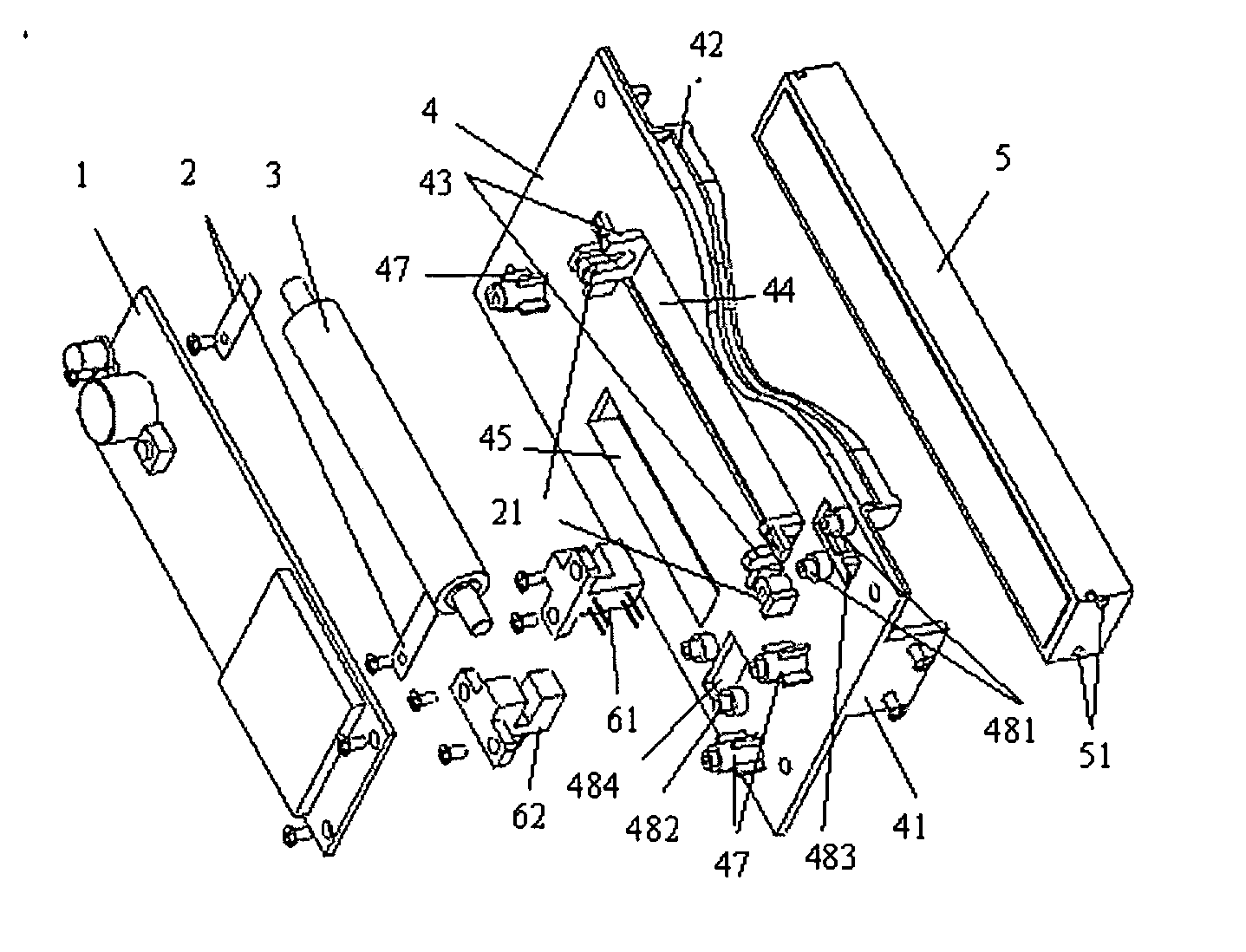
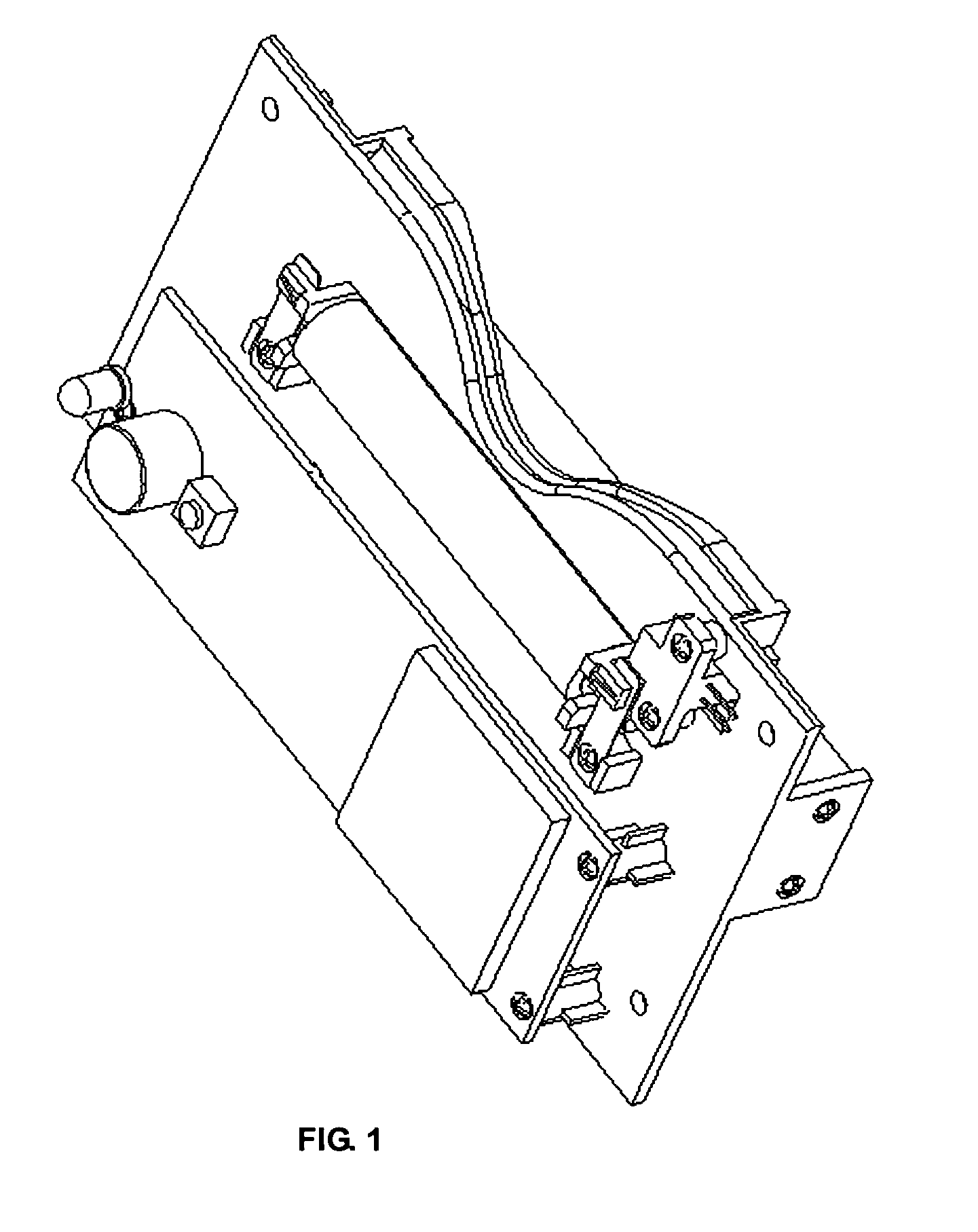
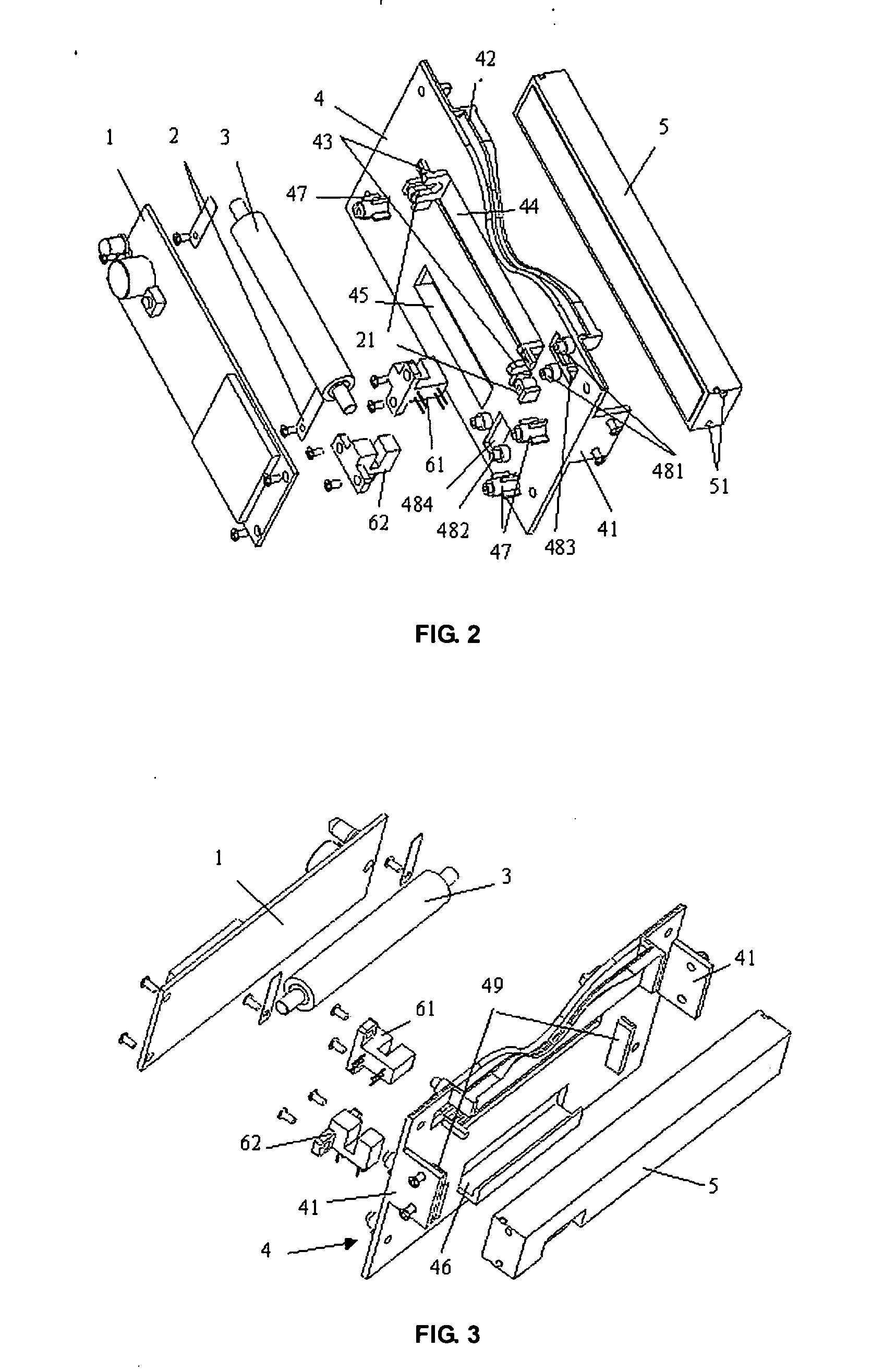
[0020] The present invention will now be described in detail in terms of its preferred embodiment and the accompanying drawings. Hereinafter, the mechanical construction of an embodiment according to the present invention will be explained in detail with reference to FIG. 1, FIG. 2 and FIG. 3. The part numbers in FIG. 2 and FIG. 3 are illustrated as follows. [0021]1. Printed Circuit Board (PCB); [0022]2. Spring tab; [0023]3. Roller; [0024]4. Body support; [0025]5. Contact Image Sensor (CIS) component module.

And the principle constructional relation is illustrated as follows.

[0026] PCB 1 is fixedly mounted on three locating poles 47 of the body support 4 with screws.

[0027] Two spring tabs 2 are respectively mounted on two locating poles 21 of the body support 4.

[0028] The roller 3 is mounted on the two U-shaped grooves 43 of the body support 4 and, under the elastic force of the two spring tabs 2, presses the inserted card onto the surface of the CIS component module 5 through t...


PUM


Abstract

An insert-type barcode reader has a body support with an insertion slot for receiving a card with barcode. A circuit board and a CIS component module electrically connected to the circuit board with each mounted to the body support to scan and process signals. A roller is mounted to the body support for movement relative to the CIS component module to allow the card to be properly guided into the insertion slot and tightly pressed onto the CIS component for accurate scanning of the barcode on the card. Two photoelectric sensors mounted to the body support are electrically connected to the circuit board for sensing the card entering and leaving the insertion slot to control starting, running and stopping of the scanning function of the CIS component module.

Description

BACKGROUND OF THE INVENTION [0001] 1. Field of the Invention [0002] The present invention relates to the field of barcode readers and, in particular, to an insert-type barcode reader for scanning and decoding barcode on card in an insertion slot through contact image sensors (CIS). [0003] 2. Description of the Prior Art [0004] With wide application of barcode technologies to the field of automatic recognition in all industries, various barcode readers are needed. Existing flatbed scanner has simplex function and is not convenient for reading barcode symbols. The sheeffed scanner is complicated to manipulate and has slow scanning speed. The flatbed scanner and the sheeffed scanner cannot be readily integrated into other equipments, which restricts their function. [0005] For a barcode on a smart card with a unified specification, there is a need for an easy-to-manipulate, high-speed-to-scan-and-decode, compact insert-type reader which can also be easily integrated into other equipment...

Claims


Application Information

Patent Timeline
IPC IPC(8): G06K7/10G06K13/08
CPCG06K13/08G06K7/10831
Inventor AN, BOGU, CHENGWULV, YINGFENGZHANG, FUDING, XIAOYUN
Owner SHENZHEN SYSCAN TECHC CO LTD
Learn More