Vacuum fluorescent display

a fluorescent display and vacuum technology, applied in the direction of luminescent screens of discharge tubes, electrical connections of cathode-ray/electron beam tubes, tubes with screens, etc., can solve the problem of difficulty in further enlarge the display region of vacuum fluorescent displays

Inactive Publication Date: 2005-06-30
NORITAKE ITRON CORP +1
View PDF1 Cites 7 Cited by
  • Summary
  • Abstract
  • Description
  • Claims
  • Application Information

AI Technical Summary

Problems solved by technology

It is difficult to further enlarge the display region of the vacuum fluorescent display 100.

Method used


Image

  • Vacuum fluorescent display
  • Vacuum fluorescent display
  • Vacuum fluorescent display

Examples


Embodiment Construction

[0019] The present invention will be described in detail with reference to the accompanying drawings.

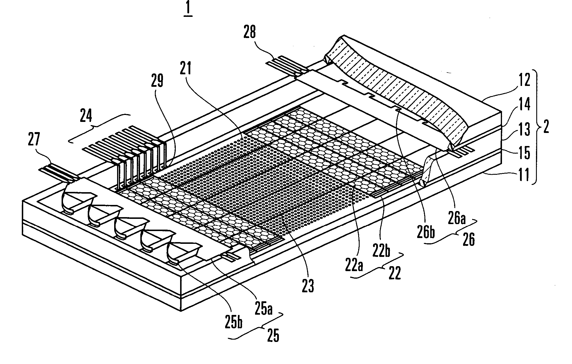
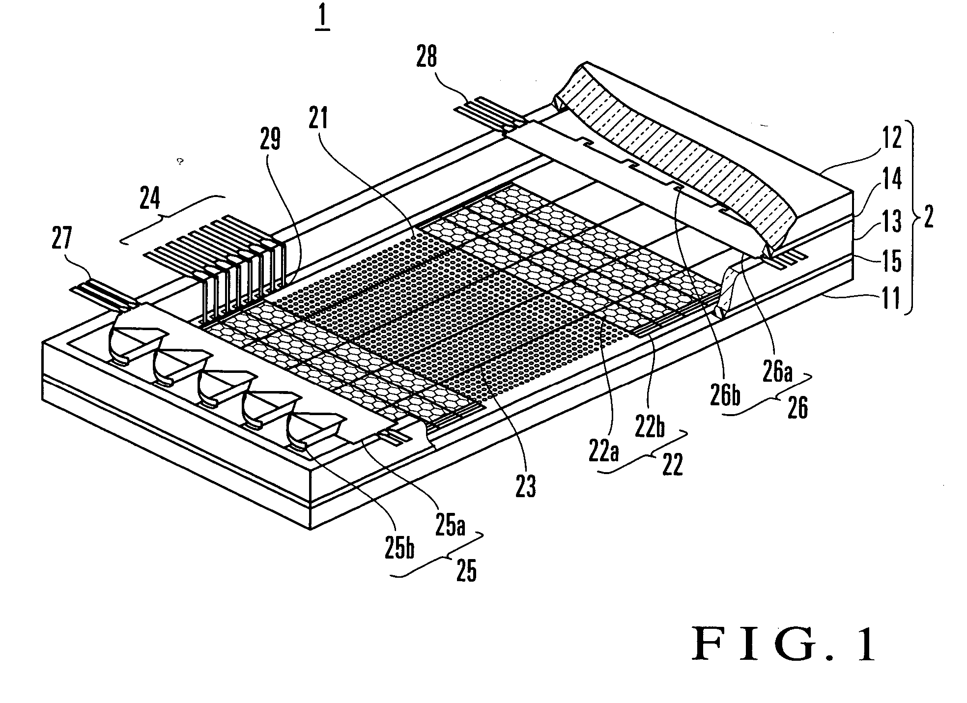
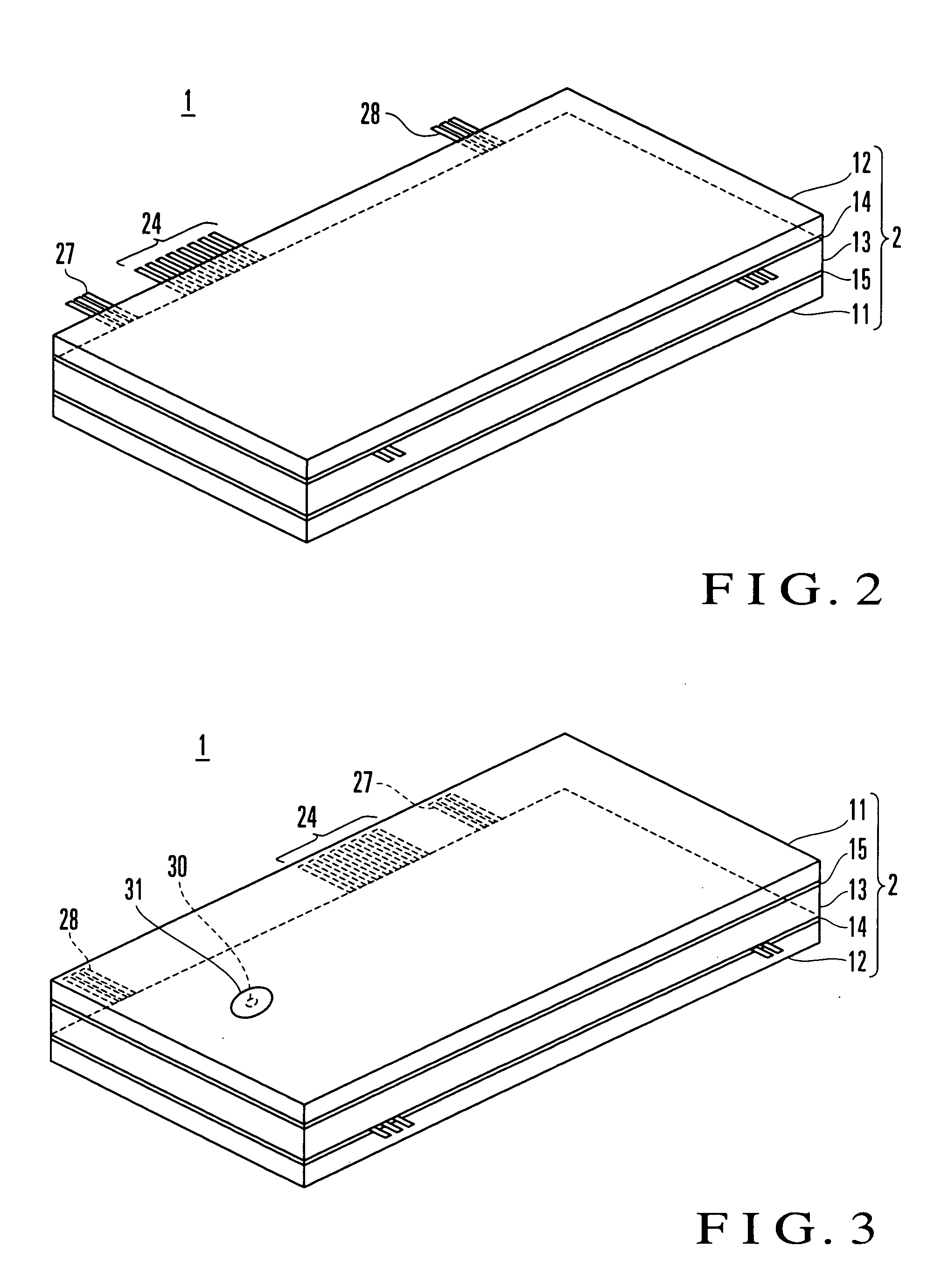
[0020] FIGS. 1 to 3 show a vacuum fluorescent display according to an embodiment of the present invention. A vacuum fluorescent display 1 has an envelope 2 including a substrate 11 such as a glass plate, an at least partly transparent front glass plate 12, and a glass spacer 13 which is arranged at the peripheral portion of the substrate 11 and opposes the substrate 11 and front glass plate 12 to each other at a predetermined gap. The substrate 11 or front glass plate 12 and the glass spacer 13 are adhered and fixed to each other through known frit glass portions 14 and 15. In the envelope 2, electrical wiring lines are formed on the substrate 11. An insulating film is then arranged on the electrical wiring lines. The electrical wiring lines have a plurality of anodes (not shown) connected through, e.g., through holes. The anodes form a predetermined pattern. In this example, the an...


PUM


Abstract

A vacuum fluorescent display includes a display portion, filament cathode, grid, and a pair of filament support members. The display portion is arranged on a substrate and has an anode coated with a phosphor material in accordance with a pattern to be displayed. The filament cathode is applied above the anode of the display portion to be separate from the anode. The grid is arranged between the anode of the display portion and the filament cathode, and cooperates with the corresponding anode to display a predetermined pattern. The pair of filament support members are connected to an outside and extend the filament cathode. Part of the filament support members is clamped between a front glass plate and glass spacer and is extracted to outside.

Description

BACKGROUND OF THE INVENTION [0001] The present invention relates to a vacuum fluorescent display in which cathodes, grids, and anodes coated with phosphors are accommodated in a vacuum-evacuated envelope. [0002]FIG. 6 shows a conventional flat type vacuum fluorescent display. Referring to FIG. 6, a vacuum fluorescent display 100 includes a substrate 111, an at least partly transparent front glass plate 112, and a glass spacer 113 arranged between the substrate 111 and front glass plate 112. The substrate 111, front glass plate 112, and glass spacer 113 are adhered to each other through frit glass portions 114 and 115 to form an envelope 101. In the envelope 101, wiring lines (not shown) are printed on the substrate 111, a plurality of anodes are arranged on the wiring lines through an insulating layer (not shown), and phosphors are attached to the anodes. The plurality of anodes form display portions 121 that can display a predetermined pattern. The plurality of anodes are disposed ...

Claims


Application Information

Patent Timeline
Patent Type & Authority Applications(United States)
IPC IPC(8): H01J31/15H01J29/90H01J29/92H01J31/12
CPCH01J29/90H01J29/92H01J2329/92H01J2229/927H01J2329/90H01J31/123
Inventor MAEDA, TADAMIOKUYAMA, KOUICHI
Owner NORITAKE ITRON CORP
Why Eureka
Try Eureka